
Hand high-lift operation riser

A high-altitude operation and lifter technology, applied in the direction of hoisting device, clockwork mechanism, etc., can solve the problems of workers falling and dying, unfavorable promotion and use, inconvenient use, etc., to ensure safety performance, light weight, easy to carry and effect used

Inactive Publication Date: 2008-10-01
张敏
View PDF0 Cites 3 Cited by
  • Summary
  • Abstract
  • Description
  • Claims
  • Application Information

AI Technical Summary

Problems solved by technology

The earliest elevators were very simple, and generally only used hanging plates hung by nylon ropes. When it was necessary to descend, the rope buckle was slowed down by hand to make the rope lengthen. This kind of equipment is relatively simple and has a poor safety factor. There will be accidents where workers fall and die due to loose buckles
For this reason, a kind of new high-altitude operation hoist has appeared in recent years, and its whole device is made up of suspension device and operating platform, and one end of steel wire rope is fixed on the steel rope holder that can rotate horizontally in the walking mechanism of suspension device, and another One end is fixed to the winding reel on the output shaft of the reduction mechanism on the operating platform through a pulley block. The chain transmission mechanism similar to a bicycle can drive the reduction gear forward and reverse, so as to realize the lifting of the operating platform. Although the lifter improves the safety factor, the structure is complicated. , it is very inconvenient to use. In addition, its production cost is relatively high, which is not conducive to widespread promotion and use.

Method used


Image

  • Hand high-lift operation riser
  • Hand high-lift operation riser
  • Hand high-lift operation riser

Examples


Embodiment Construction

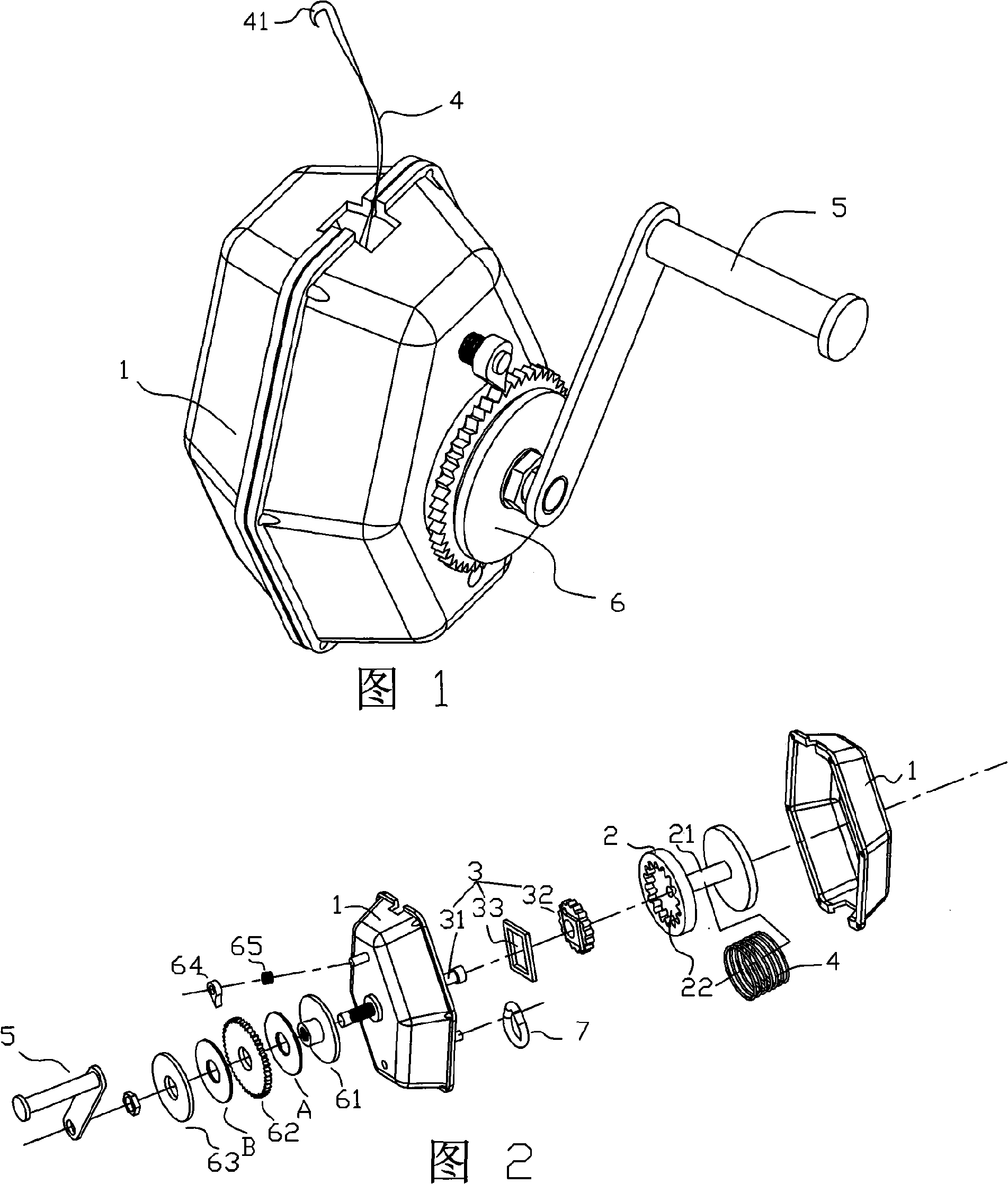
[0018] As shown in Figure 1, a hand-operated lift for aerial work, the whole device includes a housing 1, a reel 2 and a transmission mechanism 3 coaxially connected with the reel.

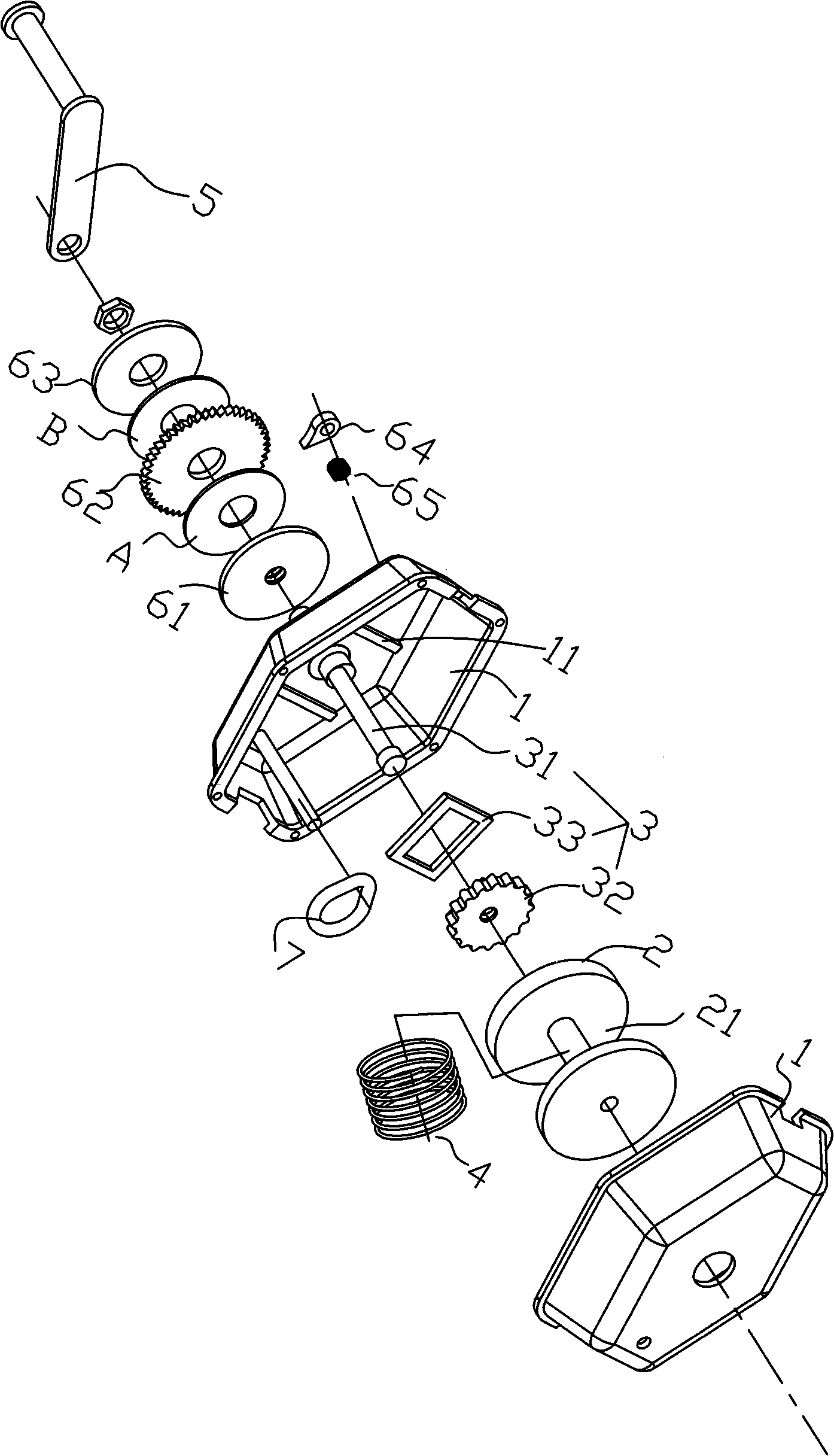
[0019] As shown in Figures 2 and 3, a groove 21 is set on the reel 2, and the steel cable 4 is wound on the groove 21. When in use, it is only necessary to engage the grab 41 with the fixed hook on the building. At the same time, there is a rotary ring gear 22 on one side of the mandrel 2 .

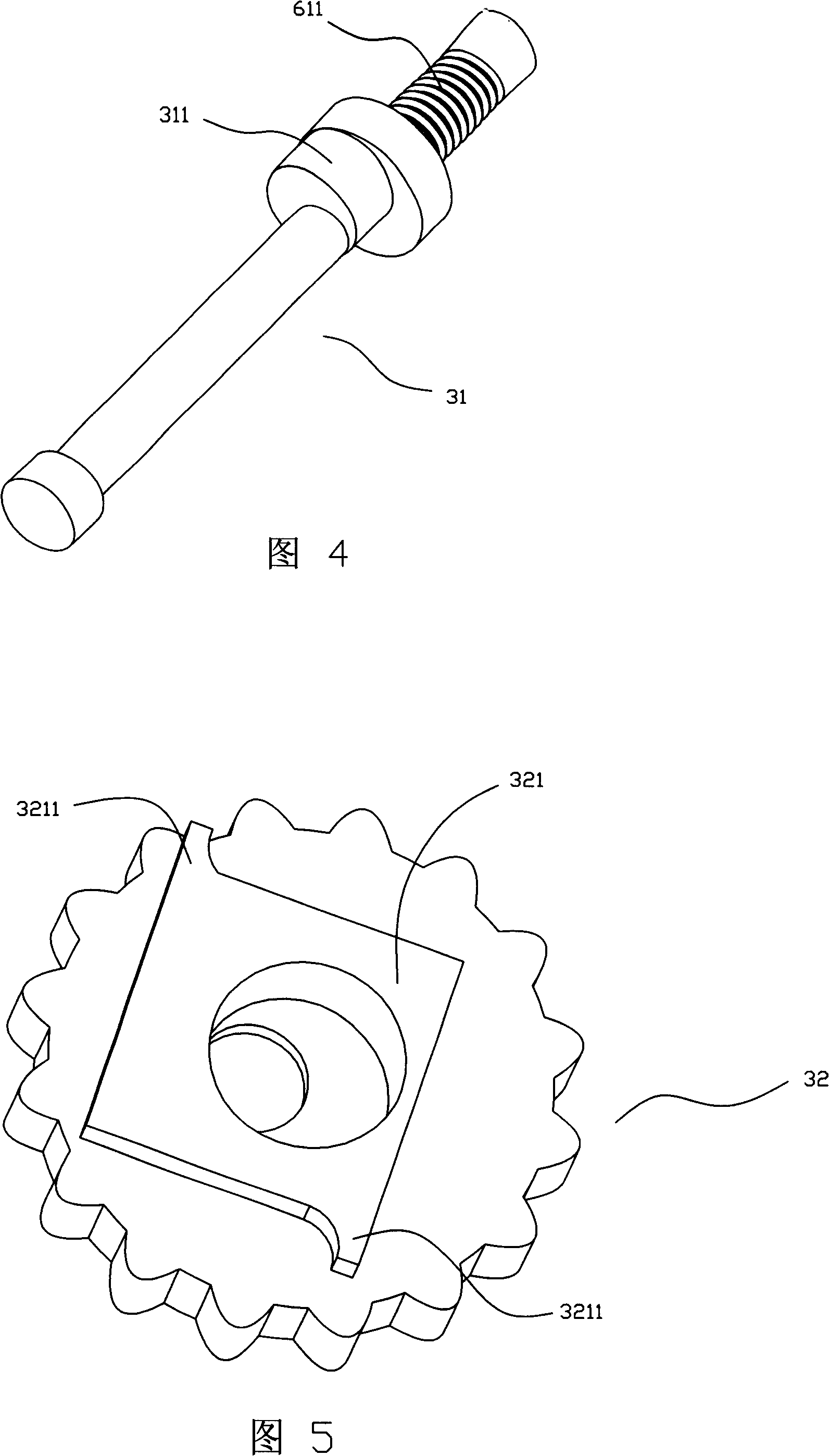
[0020] As shown in Figures 2, 3, 4 and 5, the transmission mechanism 3 includes a stepped transmission shaft 31, one end of the transmission shaft 31 passes through the central hole of the reel 2 and is positioned on the housing 1, and the other end extends out of the housing 1 is connected with hand crank 5. Simultaneously, transmission shaft 31 is provided with an eccentric wheel 311 structure in the middle part, and pinion gear 32 is installed on it, and pinion gear 32 is meshed with the rotary ring gear...


PUM


Abstract

The invention relates to a hand-operated lifting device for work high above the ground. The entire lifting device comprises a shell, a reel and a transmission mechanism coaxially connected with the reel, wherein, a groove is arranged on the reel and wound with a steel cable, the head part of which stretches out of the shell and the end part of which is provided with a grab, one side of the reel is cut with an inner revolving ring gear; the transmission mechanism comprises a step-shaped transmission shaft, one end of which passes through the central hole of the reel and is positioned on the shell while the other end thereof stretches out of the shell to be connected with a hand-operated crank; an eccentric wheel structure, on which a pinion gear is positioned is arranged at the middle part of the transmission shaft and the pinion gear is meshed with the inner revolving ring gear of the reel at the side of the maximum eccentric diameter of the eccentric wheel. The lifting device of the invention overcomes the defects of the current lifting devices and is characterized by short transmission chains and convenient adjustment for deceleration, and also has the advantages of small volume, light weight and can meet the requirement of being used in a variety of work high above the ground.

Description

technical field [0001] The invention relates to a lifter for aerial work, in particular to a hand-operated lifter for aerial work. Background technique [0002] When repairing outdoor billboards, cleaning high-rise exterior walls or installing neon lights, workers generally use a device called a lifter for work needs. The earliest elevators were very simple, and generally only used hanging plates suspended by nylon ropes. When it was necessary to descend, the rope buckle was slowed down by hand to make the rope lengthen. This kind of equipment is relatively simple and has a poor safety factor. There will be accidents where workers fall and die due to loose buckles. For this reason, a kind of new high-altitude operation hoist has appeared in recent years, and its whole device is made up of suspension device and operating platform, and one end of steel wire rope is fixed on the horizontally rotatable steel rope holder in the walking mechanism of suspension device, and another...

Claims


Application Information

Patent Timeline
Patent Type & Authority Applications(China)
IPC IPC(8): B66D1/00B66D1/04B66D1/14B66D1/54
Inventor 张敏
Owner 张敏
Learn More