Thermal bubble spinning method and device for nano-fiber production

A technology of nanofiber and thermal foaming, which is applied in the production of complete sets of equipment for artificial threads, fiber treatment, textiles and papermaking, etc. It can solve the problems of difficult production control and complicated spinning mechanism, and achieve easy production control and simple spinning mechanism Effect

Inactive Publication Date: 2008-10-01
DONGHUA UNIV
View PDF0 Cites 20 Cited by
  • Summary
  • Abstract
  • Description
  • Claims
  • Application Information

AI Technical Summary

Benefits of technology

This patented technology allows for more tiny particles called fibers be created during cooling by injecting them into liquids stored inside tanks with an electrical current flow through it. These small fiber-formations can then spun from these solutions without any harmful chemicals being released over time.

Problems solved by technology

This patented describes how bubbles spun from polyethylene (PE) can produce fibers for various applications such as filtration membranes. To achieve these goals, there must also exist some specific conditions during manufacturing processes like adjustment of pressure, flow rate, etc., which may lead to changes in properties overtime. These issues make controllability difficult without complex equipment design.

Method used


Image

  • Thermal bubble spinning method and device for nano-fiber production
  • Thermal bubble spinning method and device for nano-fiber production

Examples


Embodiment 1

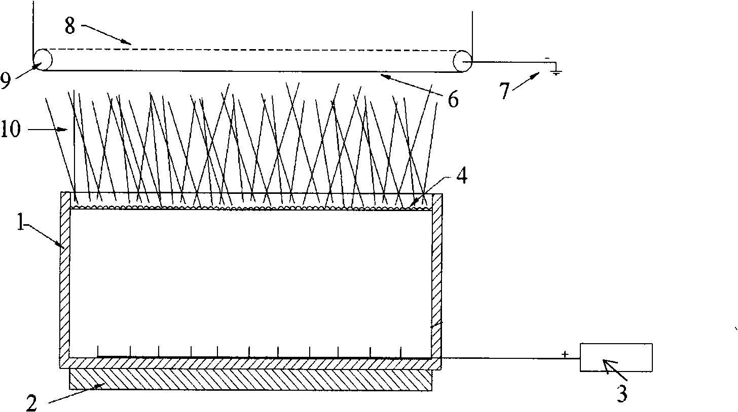
[0019] refer to figure 1 , which is a structural schematic diagram of Embodiment 1 and 2 of the present invention. The thermal foam spinning device that can be used to produce nanofibers includes a liquid storage tank 1 with an open top, and a high-voltage electrostatic generator 3 through a metal electrode and a liquid storage tank. The solution or solution 4 in the pool 1 is connected, the receiving plate 8 is grounded through the grounding electrode 7, the guide roller 9 and the receiving curtain 6 which can rotate synchronously are arranged above the liquid storage pool 1, and the receiving plate is arranged above the receiving curtain 6 8. A heating device 2 is installed at the bottom of the reservoir 1 .

[0020] First, the mass percentage is respectively 35% polyvinylpyrrolidone and 65% industrial absolute alcohol and stirs for 2.5 hours, then it is poured into the reservoir 1; open the heating device 2, and the temperature of the polyvinylpyrrolidone solution rises to ...

Embodiment 2

[0022] refer to figure 1 , is the structure diagram of Embodiment 1 and 2 of the present invention, wherein the polyvinyl alcohol solution is composed of 6% polyvinyl alcohol and 94% industrial pure water in a mass fraction ratio, the stirring time is 12 hours, and the temperature is 100°C. High voltage electrostatic generator 3 to 15 kV. Using exactly the same process steps as in Example 1, nanofibers were obtained.

Embodiment 3

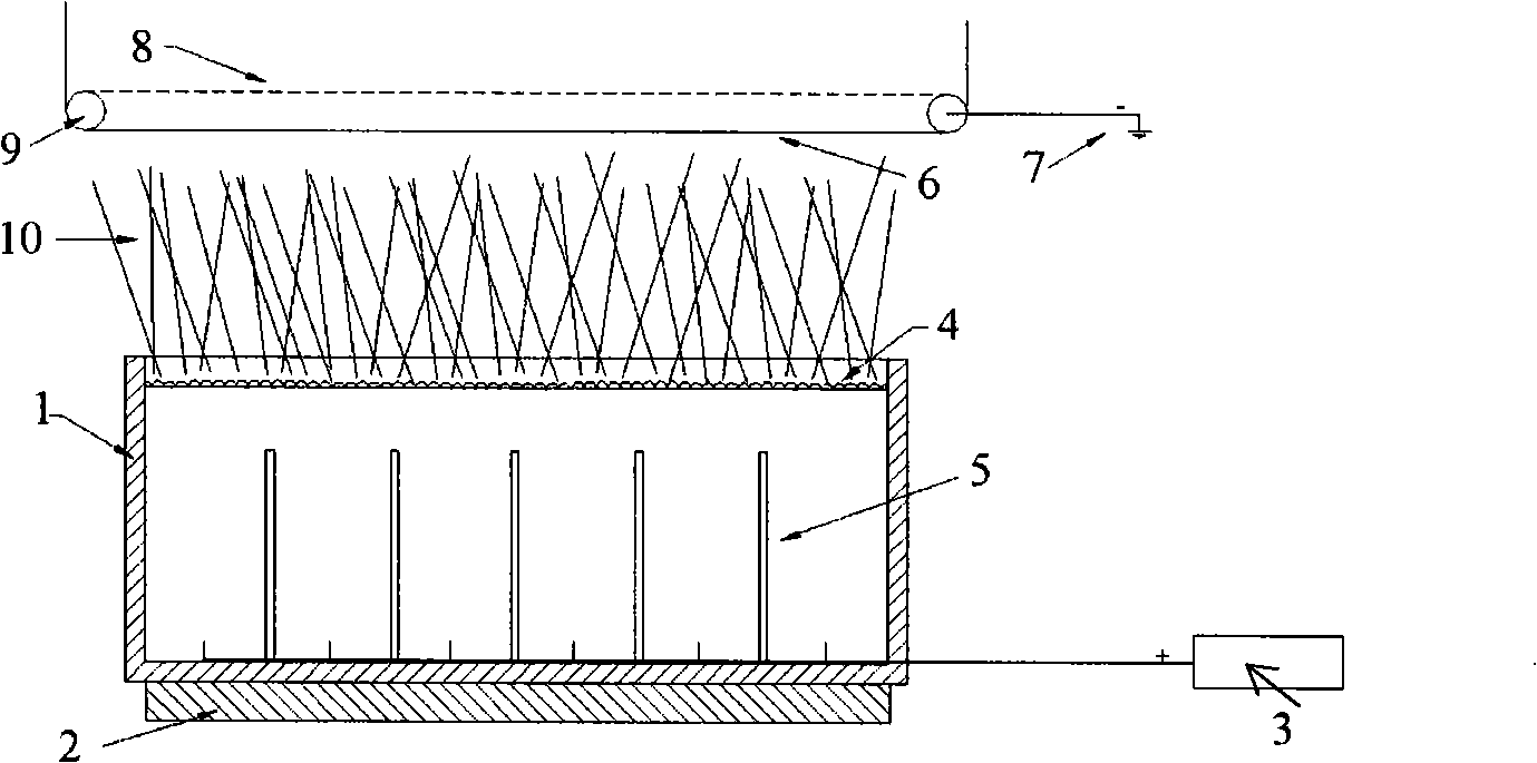
[0024] refer to figure 2 , is a schematic diagram of the structures of Embodiments 3 and 4 of the present invention. The thermal foam spinning device that can be used to produce nanofibers is composed of the gas guide rod 5 and all the components in the structure of Embodiment 1. Except for the gas guiding rod 5, the structure of embodiment 2 is completely the same as that of embodiment 1. The bottom surface of the liquid storage tank 1 is provided with a gas guiding rod 5, the purpose of which is to concentrate the gas in the solution or solution and prevent the adhesion of several liquid bubbles.

[0025] Using exactly the same process steps as in Example 1, wherein the polyacrylonitrile solution is composed of 13% polyacrylonitrile and 87% N-dimethylformamide in mass percentage, the stirring time is 48 hours, and the temperature is 150°C , adjust the high-voltage electrostatic generator from 3 to 50 kV. Using exactly the same process steps as in Example 1, nanofibers wer...


PUM


Abstract

A hubble-bubble spin method and apparatus for producing nano fibre is disclosed. The method includes the following steps: a spinning solution or dissolving body is poured in a liquid storage pool after stirring; a large amount of rule vacuole appear on the liquid level after heating, the high-pressure electrostatic generator polarization vacuole is switched on, a jet current spurts out at the top of the vacuole to shoot toward the receiving polar plate, and deposits at a receiving curtain between the solution liquid level and the receiving polar plate. The apparatus is composed of a liquid storage pool, a heating mechanism, a high-pressure electrostatic generator, the receiving polar plate, an orienting roll, an earth electrode and the receiving curtain, wherein, the heating mechanism is at the bottom of the liquid storage pool, the high-pressure electrostatic generator is connected to the solution or dissolving body in the liquid storage pool the metallic electrode, thereby forming a positive pole, the receiving polar plate is earthed through the earth electrode to form a negative pole, and the receiving polar plate, the orienting roll and the receiving curtain are provided above the liquid storage pool. The invention possesses the advantages of simple spinning mechanism, and being easy to carry out actual production control.

Description


Claims


Application Information

Patent Timeline
Owner DONGHUA UNIV
Why Eureka
Try Eureka