Ultrasonic transmitter/receiver and ultrasonic flowmeter using the same

An ultrasonic and transceiver technology, applied in the field of ultrasonic transceivers, can solve the problems of reduced transceiver characteristics, damage to the matching layer, damage, etc., and achieve the effects of stable sending and receiving of ultrasonic waves, accurate flow measurement, and prevention of damage such as fragments or cracks

Inactive Publication Date: 2008-10-01
PANASONIC CORP
View PDF2 Cites 7 Cited by
  • Summary
  • Abstract
  • Description
  • Claims
  • Application Information

AI Technical Summary

Problems solved by technology

[0006] However, in the structure of the above-mentioned existing ultrasonic transceiver, since the surface or end of the matching layer bonded to the top outer wall surface of the housing is exposed, it may be affected by people's fingers and The matching layer is damaged due to direct contact, or the matching layer is damaged due to the attachment of foreign objects or the drop of the ultrasonic transceiver, etc., so the output characteristics of the ultrasonic transceiver may be abnormal or the ultrasonic output characteristics may not show normal sensitivity.
[0007] Moreover, in the method of directly applying a protective film on the surface of the matching layer in order to prevent damage to the matching layer, in order to reduce the transmission and reception characteristics of the ultrasonic vibrator, it is necessary to design and selectively apply it to the matching layer according to the frequency of the ultrasonic waves used. The appropriate material and thickness of the protective film, so there is a problem that the setting of coating conditions and the operation management of coating conditions are more difficult, and when the vibration limiting body is installed on the side wall of the matching layer, although it can be suppressed The lateral vibration of the matching layer prevents unnecessary vibration modes, but there is a problem that mechanical damage to the surface of the matching layer cannot be effectively prevented

Method used


Image

  • Ultrasonic transmitter/receiver and ultrasonic flowmeter using the same
  • Ultrasonic transmitter/receiver and ultrasonic flowmeter using the same
  • Ultrasonic transmitter/receiver and ultrasonic flowmeter using the same

Examples


no. 1 approach

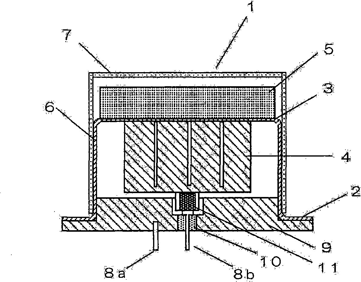
[0043] figure 1 It is a cross-sectional view showing the ultrasonic transceiver according to the first embodiment of the present invention.

[0044] exist figure 1 Among them, the ultrasonic transceiver 1 is composed of a piezoelectric body 4, an acoustic matching layer 5, and a protective cover 7, wherein the piezoelectric body 4 is bonded to the cylindrical housing 2 formed of a conductive material by epoxy resin or the like. On the inner surface of the top 3, the acoustic matching layer 5 is bonded on the outer surface of the top 3, and the protective cover 7 is kept at a predetermined distance from the surface of the acoustic matching layer 5 and along the side wall of the cylindrical housing 2 6 is fitted integrally therewith.

[0045] The structure of the acoustic matching layer 5 is: in the ceramic porous body with pores, dry gel of organic glass is permeated on the pores. In order to bond and fix the acoustic matching layer 5 and the top 3 of the cylindrical case ...

no. 2 approach

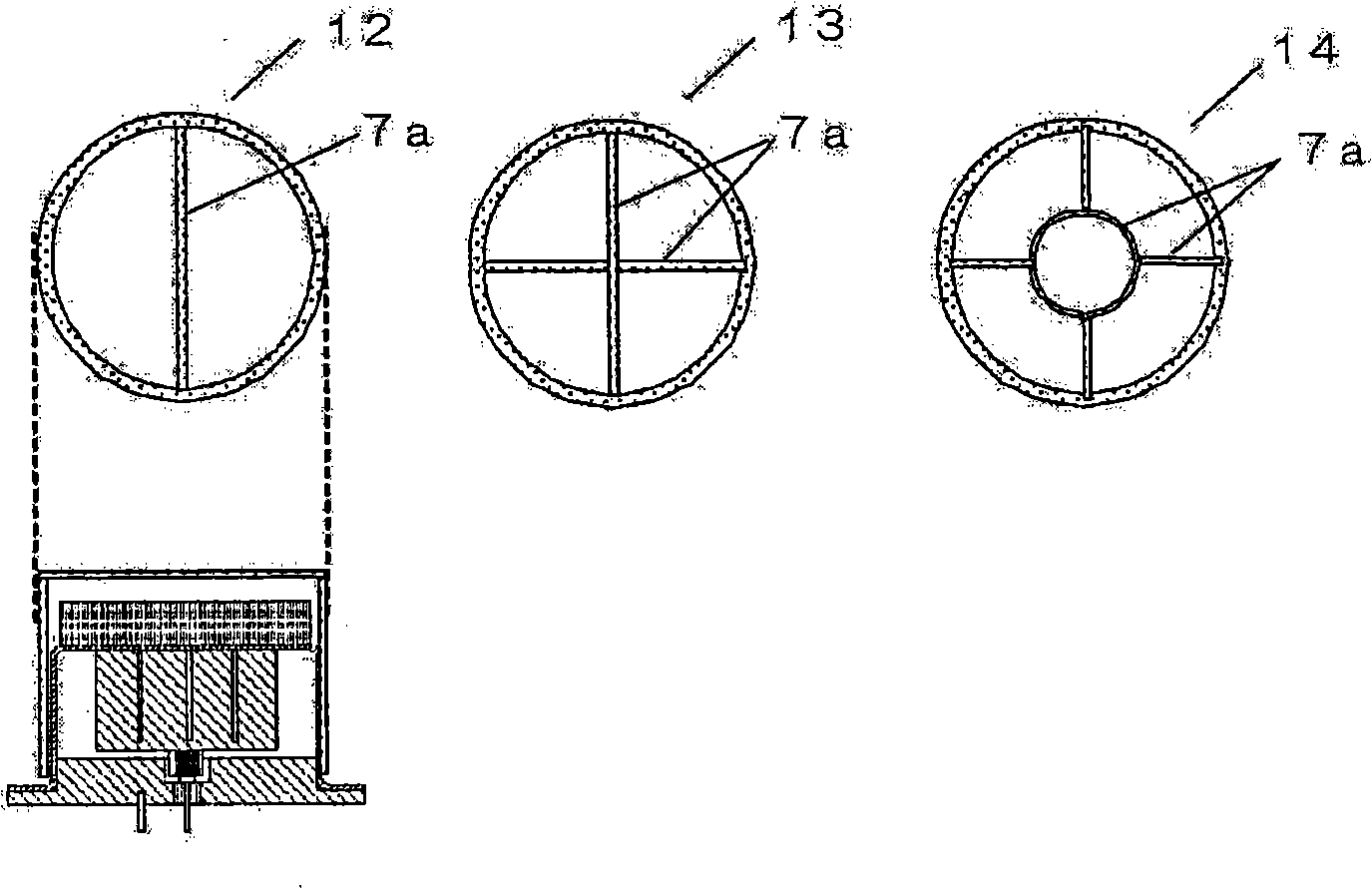
[0074] Figure 6 It is a perspective view of the ultrasonic transceiver mounted with the inline protective cover 12 according to the second embodiment of the present invention viewed from above.

[0075] Figure 6 The in-line protective cover 12 is arranged on the surface of the matching layer 5 bonded on the top 3 of the cylindrical case 2 of the ultrasonic transceiver 1 . exist Figure 6 In FIG. 3 , for convenience of description, the bonding surface of the piezoelectric body 4 bonded to the inside of the cylindrical case 2 with epoxy resin is shown in perspective.

[0076] Such as Figure 6 , Figure 7 As shown, grooves are provided on the vibrating surface of the piezoelectric body 4 used in the ultrasonic transceiver 1 and bonded to the inner surface of the cylindrical case 2 . In a rectangular parallelepiped piezoelectric body, the ultrasonic waves transmitted from the piezoelectric body cannot be efficiently transmitted and received because thickness longitudinal vib...


PUM


Abstract

The purpose of the invention is improving the environment-tolerated performance for the matching layer in a supersonic wave transceiver and maintaining the transceiving characteristic of the supersonic wave transceiver. The supersonic wave transceiver of the invention and the piezoelectrics (4) which is arranged at the top inner surface of a metal columnar shell (2) have the electronically-connecting state; and the top of the supersonic wave transceiver in the sealing state is arranged with the vocal matching layer (5) formed by the porous bodies for improving the sensibility for receiving the supersonic wave; the supersonic wave transceiver (1) has a protective cover (7) for covering the lateral wall periphery of the metal columnar shell (2) and the vocal matching layer (5); the top of the protective cover (7) can form the shielding potion for avoiding the destroy of the vocal matching layer (5) in the range of stated opening area which can assure the area of the relevant vocal matching layer (5).

Description

technical field [0001] The present invention relates to an ultrasonic transceiver used in an ultrasonic flowmeter or the like for measuring fluid flow. Background technique [0002] In the past, such ultrasonic transceivers, such as Figure 10 As shown, on the cover of the conductive airtight housing 23, the square column-shaped piezoelectric element 24 is fixed on the inner wall surface of the cover with an adhesive, and the matching layer 25 is fixed on the above-mentioned cover with an adhesive. On the outer wall surface of the cover, required wiring and drive terminals are formed in the lower open portion of the airtight case 23 to constitute the ultrasonic transceiver 26 . Here, the matching layer 25 has a structure in which a first layer made of a porous body and a second layer of a filler are laminated (for example, refer to Patent Document 1). [0003] And there is the following structure: such as Figure 11 The structure in which a protective film 27 formed of epo...

Claims


Application Information

Patent Timeline
Patent Type & Authority Applications(China)
IPC IPC(8): G01F1/66
Inventor 伊藤雅彦重冈武彦中野慎
Owner PANASONIC CORP
Why Eureka
Try Eureka