Ultrasonic device and ultrasonic apparatus
An ultrasonic and device technology, applied in the field of ultrasonic devices and ultrasonic devices, can solve problems such as obstruction of piezoelectric bodies, deformation of vibration parts, reduction of transmission and reception sensitivity, reduction of ultrasonic transmission sensitivity and reception sensitivity, etc., to achieve high-precision ultrasonic measurement and improve transmission and reception sensitivity. Effect
- Summary
- Abstract
- Description
- Claims
- Application Information
AI Technical Summary
Problems solved by technology
Method used
Image
Examples
no. 1 approach
[0055] Next, the ultrasonic measurement device according to the first embodiment will be described based on the drawings.
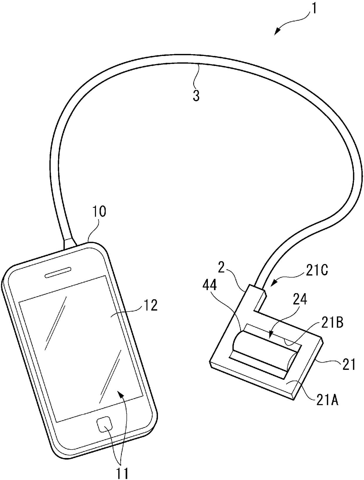
[0056] figure 1 It is a perspective view showing a schematic configuration of the ultrasonic measuring device 1 .
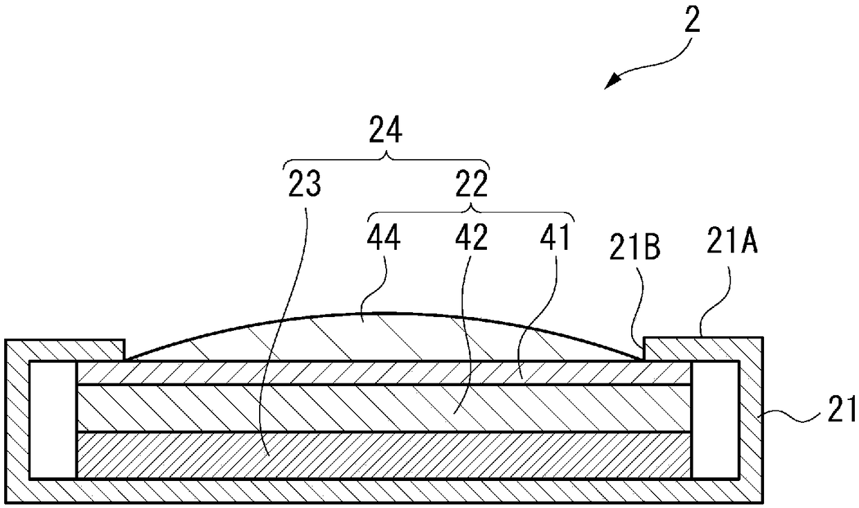
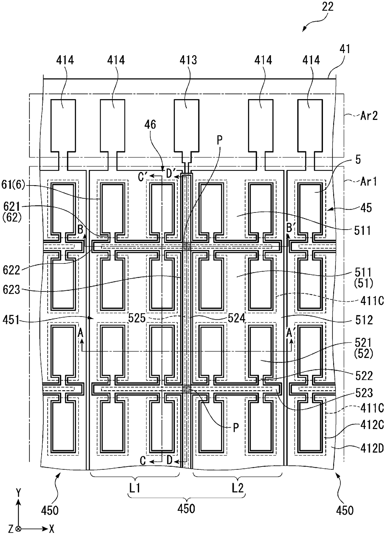
[0057] like figure 1 As shown, the ultrasonic measuring device 1 includes: an ultrasonic probe 2 ; and a control device 10 electrically connected to the ultrasonic probe 2 via a cable 3 .
[0058] This ultrasonic measurement device 1 brings an ultrasonic probe 2 into contact with the surface of a living body (for example, a human body), and transmits ultrasonic waves from the ultrasonic probe 2 into the living body. Ultrasonic waves reflected by organs in the living body are received by the ultrasonic probe 2, and based on the received signals, for example, internal tomographic images in the living body are obtained and states of organs in the living body (eg, blood circulation, etc.) are measured.
[0059] [Configuration of the control d...
no. 2 approach
[0141] Next, a second embodiment will be described.
[0142] In the ultrasonic device of the first embodiment, a plurality of ultrasonic transducers 45 constituting the ultrasonic transducer unit 450 are connected in parallel. On the other hand, the second embodiment is different in that some of the plurality of ultrasonic transducers are connected in series.
[0143] In addition, in the following description, the same code|symbol is attached|subjected to the same structure as 1st Embodiment, and the description is abbreviate|omitted or simplified.
[0144] [Structure of Ultrasonic Device]
[0145] Figure 9 It is a diagram schematically showing the element substrate 41 constituting the ultrasonic device 22A when viewed from the sealing plate 42 side. in addition, Figure 10 is schematically shown along the Figure 9 A cross-sectional view of a cross-section of the ultrasonic device 22A taken along line E-E' is shown. in addition, Figure 11 is schematically shown along...
no. 3 approach
[0189] Next, a third embodiment will be described.
[0190] In the ultrasonic devices according to the first embodiment and the second embodiment, the lead-out portion, which is smaller in width than the active portion of the piezoelectric film and has a substantially rectangular shape in plan view, is led out from the active portion. On the other hand, the third embodiment differs from the first and second embodiments in that the lead-out portion has a connecting portion whose width dimension increases toward the active portion.
[0191] In addition, in the following description, the same code|symbol is attached|subjected to the same structure as 1st Embodiment, and the description is abbreviate|omitted or simplified.
[0192] Figure 14 It is a top view schematically showing the ultrasonic transducer 49 of the third embodiment.
[0193] In the ultrasonic transducer 49 , the lead-out portion 62 has a connection portion 624 connected to the active portion 61 .
[0194] In a...
PUM
 Abstract
Description
Claims
Application Information
 - R&D
- Intellectual Property
- Life Sciences
- Materials
- Tech Scout
- Unparalleled Data Quality
- Higher Quality Content
- 60% Fewer Hallucinations
Browse by: Latest US Patents, China's latest patents, Technical Efficacy Thesaurus, Application Domain, Technology Topic, Popular Technical Reports.
© 2025 PatSnap. All rights reserved.Legal|Privacy policy|Modern Slavery Act Transparency Statement|Sitemap|About US| Contact US: help@patsnap.com


