Ultrasonic vibrator element and ultrasonic endoscope
A vibrator component, ultrasonic technology, applied in ultrasonic/sonic/infrasonic diagnosis, acoustic diagnosis, electrical components, etc., can solve the problems of small opening ratio and difficult sensitivity of sending and receiving, and achieve the effect of high sending and receiving sensitivity
- Summary
- Abstract
- Description
- Claims
- Application Information
AI Technical Summary
Problems solved by technology
Method used
Image
Examples
no. 1 Embodiment approach
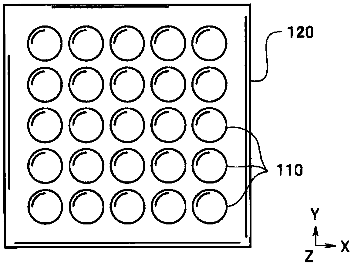
[0042] Such as Figure 4 As shown, in the ultrasonic transducer element 20 of the present embodiment, a unit group 10Z composed of a plurality of ultrasonic transducer units 10 is arranged on a substrate 11 . Then, when a drive signal is applied between the lower electrode terminal 12T and the upper electrode terminal 16T, the unit group 10Z transmits ultrasonic waves, and the incident ultrasonic waves are converted into electrical capacitance based on the change in capacitance between the lower electrode terminal 12T and the upper electrode terminal 16T. signal and is received.
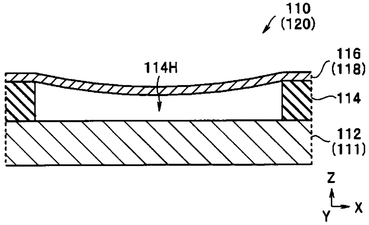
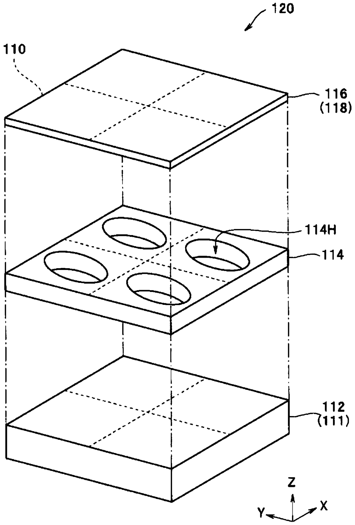
[0043] Such as Figure 5 As shown, the unit 10 has a lower electrode 12 connected to the lower electrode terminal 12T, a lower insulating layer 13 covering the lower electrode 12, a post 14 formed with a cavity 14H, and a post 14 supported by the post 14, including an upper electrode terminal 16T. The diaphragm 18 of the upper electrode 16 is connected. Diaphragm 18 in the region immediately above...
no. 2 Embodiment approach
[0077] Figure 9 The element 20A of the illustrated second embodiment is similar to the element 20 , so the same components are given the same reference numerals and their descriptions are omitted.
[0078] In the element 20A, the lower electrode 12A is a common lower electrode for a plurality of cells 10A arranged on the entire surface of the cell group 10ZA formation region. That is, in Figure 9 In , the lower electrode 12A of each cell 10A is indicated by a dotted line, but the boundary line is a phantom line.
[0079] In the element 20A, the lower electrode 12A is arranged on the entire surface, but since the area where the upper and lower electrodes face each other is the diaphragm 18, compared with the element 20 having the lower electrode 12 formed in a pattern, the insensitive area will not be affected. Increase.
[0080] Since the element 20A does not need to pattern the lower electrode 12A, it is easy to manufacture. Furthermore, as already described, since the ...
no. 3 Embodiment approach
[0084] Figure 10 The element 20B of the third embodiment shown is similar to the element 20 and the like, so the same components are given the same reference numerals and description thereof will be omitted.
[0085] Each unit 10B of the element 20B has six columns 14 exclusively. Therefore, useless regions that do not contribute to transmission and reception are formed between the cells 10B.
[0086] Among the elements 20 and the like in which the column 14 is shared by the adjacent units 10, if one column is defective, the three units 10 sharing the column are defective. On the other hand, in the element 20B, even if the column fails, only one cell 10B becomes defective, so there is a high probability that it can be used as a product. That is, in the element 20B, not necessarily all the cells 10B are good products in many cases.
[0087] The element 20B has the effect of the element 20 and the like, and its manufacturing yield is higher than that of the element 20 and the ...
PUM
 Abstract
Description
Claims
Application Information
 - R&D
- Intellectual Property
- Life Sciences
- Materials
- Tech Scout
- Unparalleled Data Quality
- Higher Quality Content
- 60% Fewer Hallucinations
Browse by: Latest US Patents, China's latest patents, Technical Efficacy Thesaurus, Application Domain, Technology Topic, Popular Technical Reports.
© 2025 PatSnap. All rights reserved.Legal|Privacy policy|Modern Slavery Act Transparency Statement|Sitemap|About US| Contact US: help@patsnap.com


