Spaceflight electronic device excess article automatic detection system and detection method

An automatic detection and electronic device technology, which is applied to the analysis of materials, ultrasonic/sonic/infrasonic generation, instruments, etc., can solve the problems of poor objectivity, low detection accuracy, and inability to judge redundant material characteristics, etc., to achieve detection Stable and reliable effect

CN101275928AInactive Publication Date: 2008-10-01HARBIN INST OF TECH
0 Cites 24 Cited by

Patent Information

Authority / Receiving Office
CN · China
Patent Type
Applications(China)
Current Assignee / Owner
Publication Date
2008-10-01
Estimated Expiration
Not applicable · inactive patent

Smart Images

  • Figure 1
    Figure 1
  • Figure 2
    Figure 2
  • Figure 3
    Figure 3
Patent Text Reader

Abstract

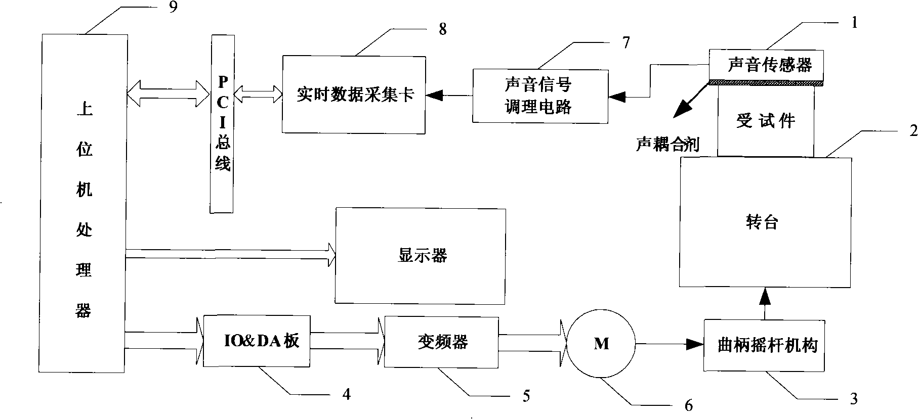
The present invention provides a system for automatically detecting the redundant object of the spaceflight electronic device and a detecting method. The system comprises the following components: a sound sensor 1, a rotating platform 2, a crank-rocker mechanism 3, an IO*amp;DA board card 4, a transducer 5, a three-phase machine 6, a sound signal regulating circuit 7, a real-time data collection card 8 and an upper machine processor 9. The sound sensor is adhibited on the external wall of the detected pice. The sound sensor 1 is connected with the sound signal regulating circuit 7 through a signal wire. The sound signal regulating circuit 7 is connected to the real-time data collection card 8. The real-time data collection card 8 is connected with the upper machine processor 9. The upper machine process 9 is connected with the control end of the transducer 5 through the IO*amp;DA board card 4. The transducer 5 is connected to the three-phase machine 6 which drives the rotating platform 2 through the crank-rocket mechanism 3. The invention settles the problems of no high detecting precision, no strong objectivity, no realization for automatic detection or automatic determining, only determination to the existence of the redundant particle, no determination to the material and characteristic of the redundant object and the like in the existing traditional PIND detection method.
Need to check novelty before this filing date? Find Prior Art

Description

(1) Technical field

[0001] The invention relates to electronic monitoring technology, in particular to an automatic detection method for redundant objects inside electronic devices. (2) Background technology

[0002] Aerospace electronic devices are widely used in military, aviation, aerospace and other national defense and military fields. Electronic devices are an important part of defense systems. Keeping electronic devices functioning properly and not failing is critical to ensuring the success of the mission and the safety of personnel and equipment. During the manufacturing and assembly process of airtight electronic devices, it is easy to encapsulate dust, plastic shavings, solder and other particles in the relay and attach to the internal components of the electronic device to form redundant particles. During the working process of electronic devices, external shocks or vibrations cause redundant objects to swim and collide randomly, which may cause device malfunct...

Examples

Embodiment Construction

[0043] The present invention will be further described below in conjunction with accompanying drawing and specific embodiment:

[0044] 1. The mechanical structure design of the turntable

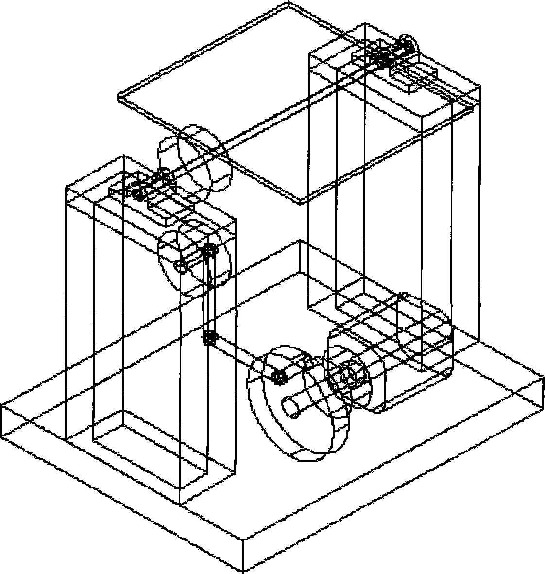
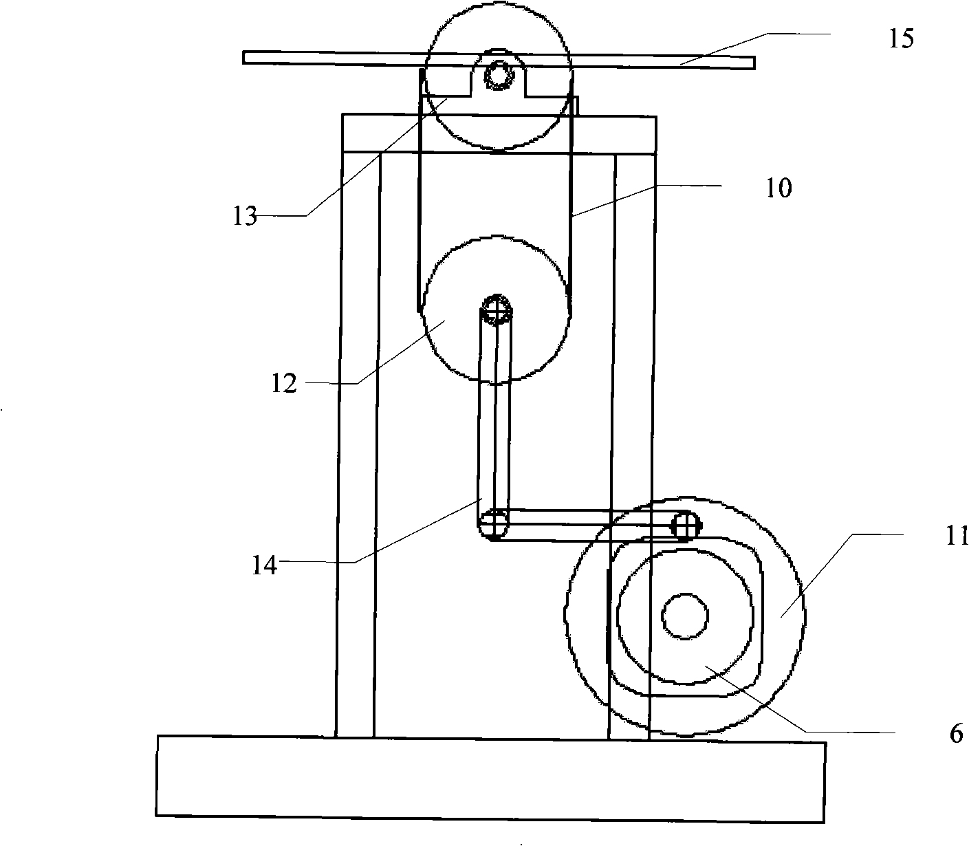
[0045] (1) combination figure 1The system composition of this embodiment includes: sound sensor 1, turntable 2, crank rocker mechanism 3, IO&DA board 4, frequency converter 5, three-phase motor 6, sound signal conditioning circuit 7, real-time data acquisition card 8 and host computer processor 9. The sound sensor 1 is attached to the outer wall of the test piece, and the sound sensor 1 is connected to the signal conditioning circuit 6 through the signal line; the signal conditioning circuit 6 amplifies the signal and outputs it through the PNC plug, and the other end of the data line is input by the DB9 plug; real-time data The acquisition card 8 is inserted into the PCI slot of the upper computer processor 9, and the signal data is sent to the upper computer processor 9 through the PCI ...