
Induction regulator for controlling energy flow used in alternating current transmission network, and method for controlling the network

A technology of transmission network and regulator, applied in the direction of AC network voltage adjustment, reactive power adjustment/elimination/compensation, reactive power compensation, etc., can solve the problems of voltage change, change of voltage phase angle, difficulty in parallel connection of lines and equipment, etc.

Inactive Publication Date: 2008-10-01
ABB RES LTD
View PDF1 Cites 0 Cited by
  • Summary
  • Abstract
  • Description
  • Claims
  • Application Information

AI Technical Summary

Problems solved by technology

[0030] The disadvantage of the inductive regulator is that the control possibilities are limited to the voltage change achieved by the secondary voltage vector and this simultaneously changes the phase angle of the voltage
This makes parallel connection of lines and equipment difficult due to angular rotation producing voltage variations and cyclical reaction effects

Method used


Image

  • Induction regulator for controlling energy flow used in alternating current transmission network, and method for controlling the network
  • Induction regulator for controlling energy flow used in alternating current transmission network, and method for controlling the network
  • Induction regulator for controlling energy flow used in alternating current transmission network, and method for controlling the network

Examples


Embodiment Construction

[0049] In the following description and figures, the invention is exemplified only for the control of a three-phase network with phases r, s, t, since in practice three-phase distribution networks are most often used, while the invention is equally applicable to networks with different numbers multiphase network of phases.

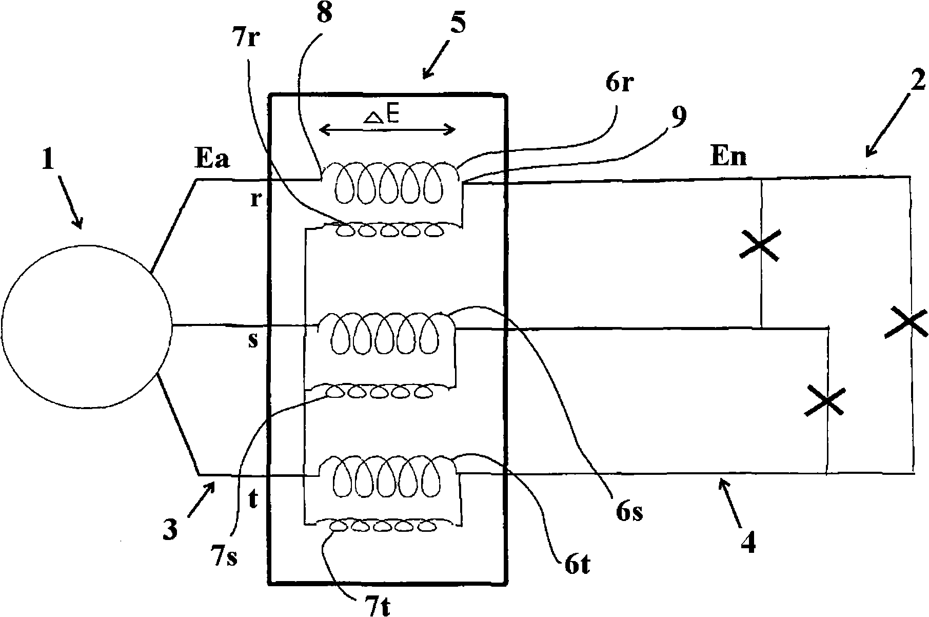
[0050] exist figure 1 In , 1 denotes a current source connected to the user 2 through its 3 phases 3r, 3s and 3t via a three-phase network showing a primary side 3 and a secondary side 4 . An inductance regulator 5 is connected between the current source and the user. Between the current source 1 and the inductance regulator 5, the phase voltage Ea in the network is variable, while the phase voltage En in the network between the inductance regulator and the user remains constant. The inductance regulator shows 3 stator windings 6r, 6s and 6t and 3 rotor windings 7r, 7s and 7t. The corresponding stator windings show a primary connection 8 connected to the ...


PUM


Abstract

A device for controlling the voltage and the phase angle of a polyphase electric transmission network (1) comprising an induction regulator (5) that is connected between the primary side (1a) and the secondary side (1b) of the transmission network. A gap (14) is provided with a magnetic layer (17) which exhibits a relative permeability ([mu]r) that is controllable, wherein the magnitude (amplitude) of the secondary voltage vector deltaE is also adapted to be controlled by controlling the permeability of the magnetic layer (17). The magnetic layer (17) may consist of a magnetic fluid or a solid material.

Description

technical field [0001] The invention relates to an inductance regulator for controlling the voltage and phase angle of a polyphase electrical transmission network, the inductance regulator being connected between the primary side and the secondary side of the transmission network and comprising a stator with stator windings and stator poles, Partially rotatable rotor with rotor windings and rotor poles, and gaps between corresponding stator poles and rotor poles. [0002] The invention also relates to a method of controlling the voltage and phase angle of a polyphase transmission network. [0003] The invention also relates to the use of power flow control devices for high voltage multiphase transmission networks. Background technique [0004] The functional flow in the ac network is governed by the following equation: [0005] P = U 1 U 2 ...

Claims


Application Information

Patent Timeline
IPC IPC(8): H02J3/12H02J3/18
CPCY02E40/30
Inventor 斯特凡·约翰松米卡埃尔·达尔格伦
Owner ABB RES LTD
Learn More