Sliding-raising mechanism of ditcher

A ditching machine, sliding warping technology, applied in the direction of excavation/covering ditches, application, planting methods, etc., can solve the problems of flameout, diesel engine speed reduction, insufficient tightening force, etc., and achieve low soil firmness and soil moisture The effect of large and small cutting resistance

Inactive Publication Date: 2008-10-08
葛玉明
View PDF1 Cites 5 Cited by
  • Summary
  • Abstract
  • Description
  • Claims
  • Application Information

AI Technical Summary

Problems solved by technology

However, because the sliding warp of the existing trencher is below the frame arm and close to the cutter head of the trencher, when this trencher is used to repeatedly ditch the old ditch, it will be close to the old trench due to the slippery warp. The edge, if you don’t pay attention, it will slip into the old ditch due to the slope of the edge of the old ditch. After sliding into the old ditch, the bottom of the ditch will suddenly become deeper, and the speed of the diesel engine will decrease due to the sudden increase of the ditching load. even turn off
On the other hand, there is only one screw on the side of the existing bushing to fasten the sliding post instead of passing through the sliding post. The tightening force is not enough, and the sliding post will slip off after loosening

Method used


Image

  • Sliding-raising mechanism of ditcher
  • Sliding-raising mechanism of ditcher
  • Sliding-raising mechanism of ditcher

Examples


Embodiment 1

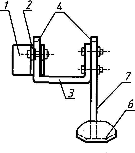
[0017] Embodiment 1. The sliding and warping mechanism of the ditching machine includes a closed casing arranged on the front end of the ditching machine frame arm 1 and a sliding and warping 6. One side of the closed casing is provided with a bolt hole and a sliding and warping post 7 is provided with a plurality of bolt holes. In addition, a U-shaped joint block 3 is provided, and the two vertical columns of the U-shaped joint block are provided with bolt holes; when a new ditch is opened in ordinary flat fields, the bolts are used to directly fix the sliding warped column on the closed casing , When it is necessary to repeat ditching to the old ditch, the U-shaped joint block is first fixed on the closed casing with bolts, and then the sliding upright column is bolted on another vertical column of the U-shaped joint block.

Embodiment 2

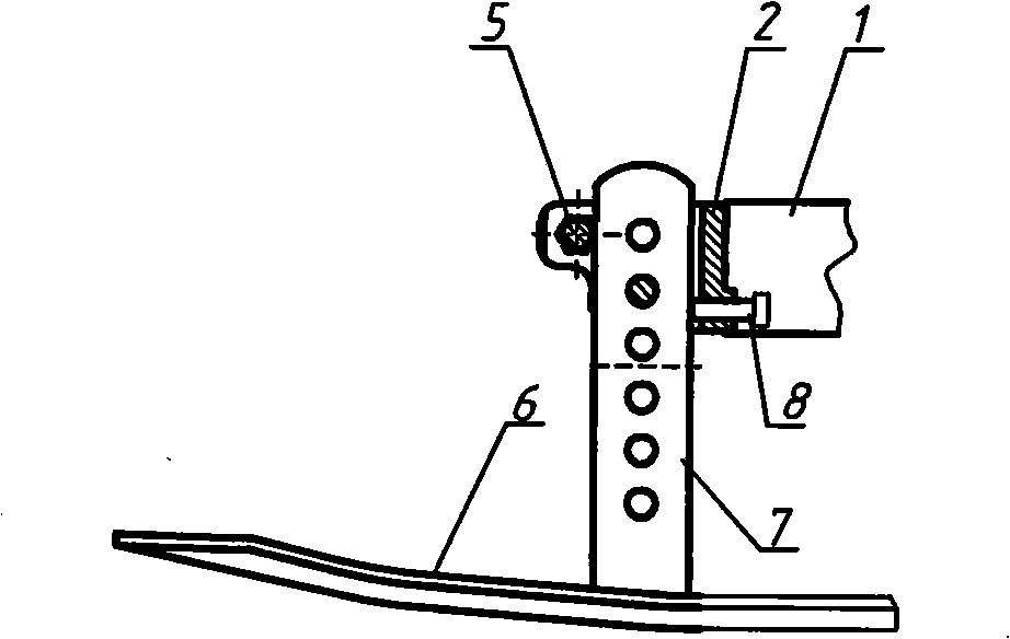
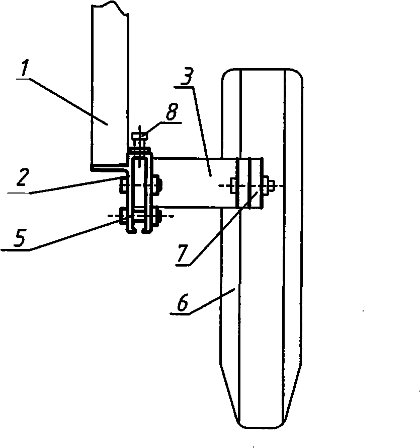
[0018] Embodiment 2, as figure 1 , 2 , 3 shown. The sliding mechanism of the ditching machine includes the sliding clip 2 and the sliding clip 6 arranged at the front end of the ditching machine frame arm 1; the front end of the sliding clip 2 is an opening, and the middle parts of both sides are symmetrically provided with bolt holes; the sliding clip Column 7 is provided with a plurality of bolt holes. Also be provided with a U-shaped connecting block 3 in addition, two vertical columns 4 of the U-shaped connecting block are provided with bolt holes; , When it is necessary to repeat the ditching of the old ditch, the U-shaped joint block is first fixed on the sliding clamp with bolts, and then the sliding vertical column is fixed on another vertical column of the U-shaped joint block with bolts. Such as Figure 4 and Figure 5 As shown, clamping bolt holes 5 are arranged symmetrically on the front of both sides of the sliding clip, and the two sides of the sliding clip ...


PUM


Abstract

The invention discloses a skidding mechanism of a ditcher, including an enclosed sleeve or a skidding clip which is arranged at the front end of a frame arm of the ditcher and a skidding plate; one side surface of the enclosed sleeve is provided with a bolt hole, a skidding pillar of the skidding plate is provided with a plurality of bolt holes; the skidding mechanism is characterized in that: a U-shaped joint block is additionally arranged, two vertical posts of the U-shaped joint block are equipped with the bolt holes; either the skidding pillar is directly fixed on the enclosed sleeve or the skidding clip by a bolt, or the U-shaped joint block is firstly fixed on the enclosed sleeve or the warping clip by the bolt and then the skidding pillar is fixed on the other vertical post of the U-shaped joint block by the bolt. The mechanism of the invention not only is adaptable for trenching new ditches on a common field, but also can solve the problem of broadening and deepening and repeated ditch in old ditches.

Description

technical field [0001] The invention belongs to the field of agricultural machinery, and relates to a sliding and warping mechanism of a farmland ditching machine which can adapt to repeated ditching in old ditches. Background technique [0002] Chinese utility model patent "farmland ditching machine" (authorization announcement number: CN2375068Y, patent number: 99228497) discloses a kind of single cantilever type farmland ditching machine, has been widely used now. The frame arm is a single cantilever structure, and there is a closed casing at the front, and the sliding column for adjusting the depth runs through the casing, and is tightened with a set bolt, and the sliding is just below the frame arm. [0003] In many areas, no-till farming is adopted in the farmland. After crops such as wheat and rapeseed are harvested, the land is no longer plowed, but the next round of crops is planted using no-till. Therefore, the ditches opened in the wheat fields of the previous yea...

Claims


Application Information

Patent Timeline
Patent Type & Authority Applications(China)
IPC IPC(8): A01C5/06
Inventor 葛玉明葛伟岸
Owner 葛玉明
Why Eureka
Try Eureka