Concrete screw structure

a screw structure and screw technology, applied in the direction of screws, threaded fasteners, fastening means, etc., can solve the problems of workpiece fracture, workpiece frictional resistance, and workpiece sway and deviation, so as to reduce cutting resistance, improve processing speed, and optimize the effect of fastening

Inactive Publication Date: 2013-11-14
BI MIRTH CORP
View PDF3 Cites 11 Cited by
  • Summary
  • Abstract
  • Description
  • Claims
  • Application Information

AI Technical Summary

Benefits of technology

[0004]To mitigate and eliminate the above disadvantages, the present invention provides an improved screw structure capable of reducing cutting resistance as well as increasing a processing speed and optimizing fastening effect.

Problems solved by technology

However, in a process of screwing a screw into a workpiece, as the circular thread of the screw, the screw is in linear or planar contact with the workpiece when cutting the workpiece, namely the screw receives greater frictional resistance from the workpiece and is prone to sway and deviate.
Further, since crumbs of the workpiece are likely accumulated when the workpiece is cut by the thread plane of the screw, more effort and time are needed for fastening.
In the event that too many crumbs are accumulated without discharging, frictional force during screwing would be increased to result in fracture of the workpiece.

Method used


Image

  • Concrete screw structure
  • Concrete screw structure
  • Concrete screw structure

Examples


Embodiment Construction

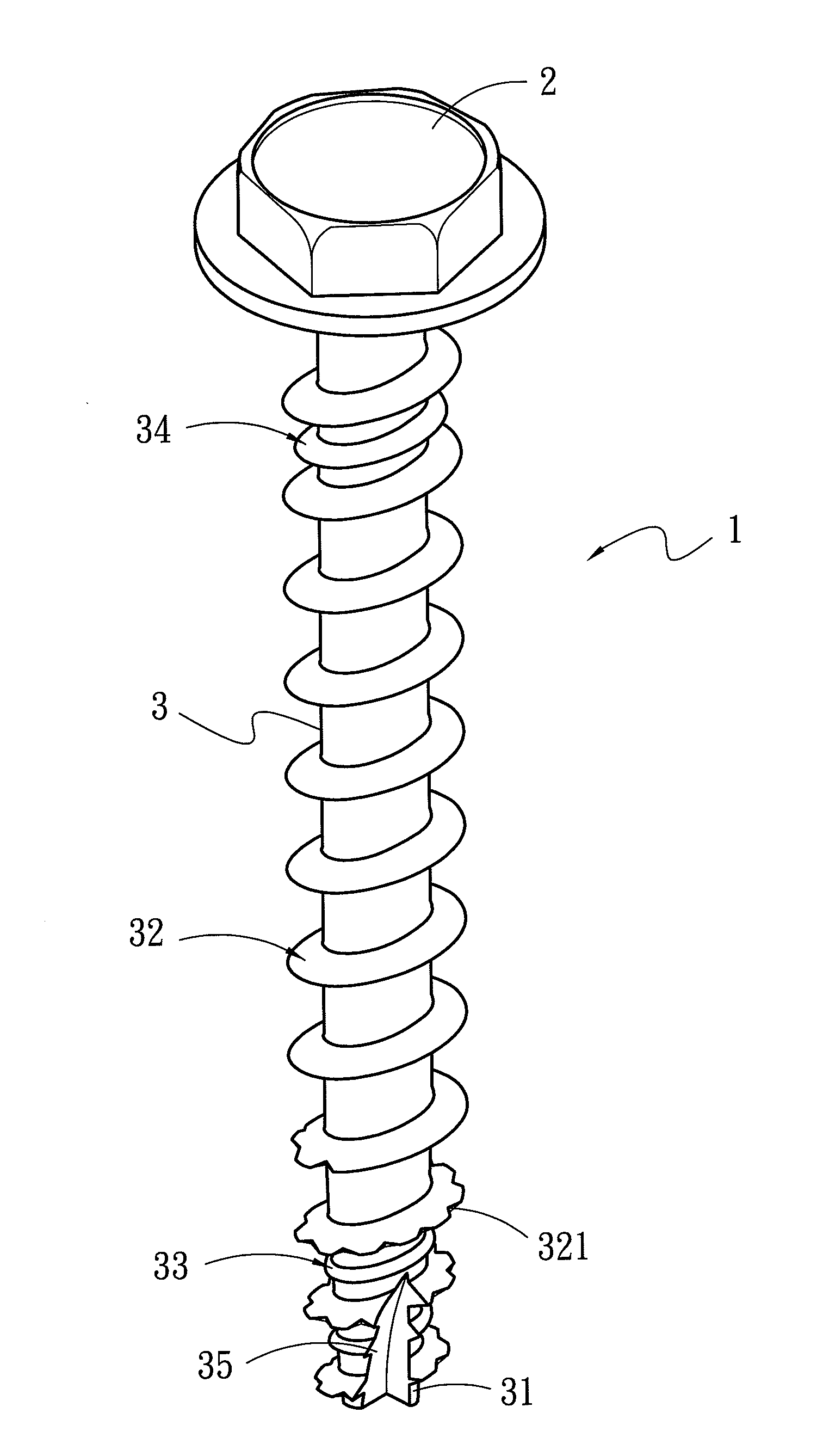
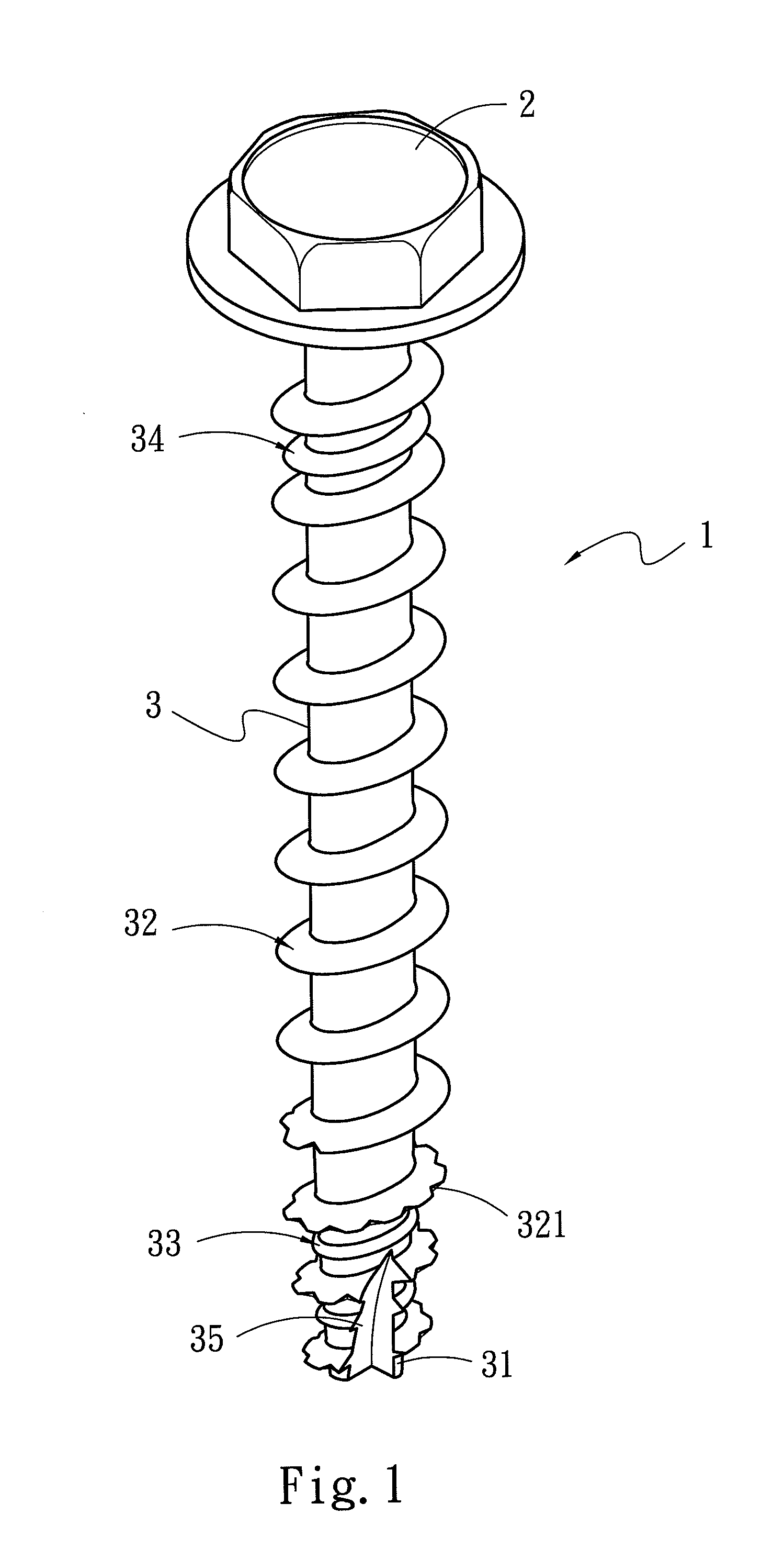
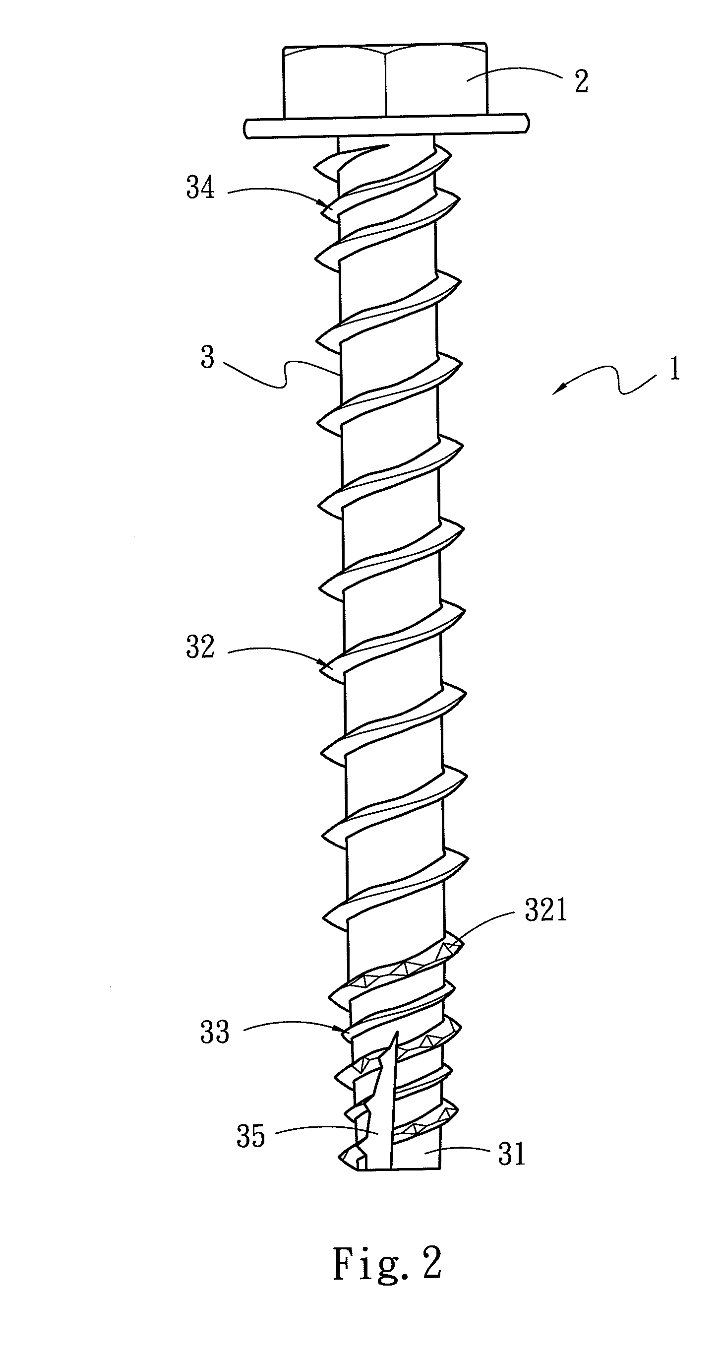
[0024]Referring to FIGS. 1, 2 and 3A, a concrete screw 1 according to one embodiment of the present invention comprises a screw head 2 and a rod 3. The rod 3 is a circular rod and is extended downwards from the screw head 2. The rod 3 comprises a drilling tail section 31 at a distal end thereof, a first thread section 32 formed annularly thereon and extended upwards from the drilling tail section 31, and a second thread section 33 encircling between at least two thread pitches of the first thread section 32. An outer diameter of the second thread section 33 is smaller than that of the first thread section 32, and is one-third of that of the first thread section 32. The rod 3 further comprises a third thread section 34 at on upper end thereof. The third thread section 34 encircles downwards between at least two thread pitches of the first thread section 32. An outer diameter of the third thread section 34 is between those of the first thread section 32 and the second thread section 3...


PUM


Abstract

A concrete screw includes a screw head and a rod with a drilling tail section at a distal end thereof. The rod includes a first thread section formed annularly thereon and extended upwards from the drilling tail section, and a second thread section encircling between at least two thread pitches of the first thread section and having an outer diameter smaller than that of the first thread section. The rod further includes a third thread section on an upper end thereof encircling between at least two thread pitches of the first thread section. As the outer edge of the second thread section butts the wall of the screw hole, the first thread section can steadily perform cutting without swaying. Moreover, through the third thread section, compact effect is thereby achieved at a position near the screw head. Hence the concrete screw can provide precise, effort-saving and steady fastening effect.

Description

FIELD OF THE INVENTION[0001]The present invention relates to a screw, and particularly to a concrete screw structure for a concrete or stone construction material.BACKGROUND OF THE INVENTION[0002]A conventional concrete screw is generally used for fastening workpieces with various types of materials, e.g., wood, plastic, metal and concrete. A screw rod of a conventional concrete screw is formed by a spiral thread section for allowing the screw to be screwed into the workpiece for fastening.[0003]However, in a process of screwing a screw into a workpiece, as the circular thread of the screw, the screw is in linear or planar contact with the workpiece when cutting the workpiece, namely the screw receives greater frictional resistance from the workpiece and is prone to sway and deviate. Further, since crumbs of the workpiece are likely accumulated when the workpiece is cut by the thread plane of the screw, more effort and time are needed for fastening. In the event that too many crumbs...

Claims


Application Information

Patent Timeline
Patent Type & Authority Applications(United States)
IPC IPC(8): F16B25/02F16B25/10
CPCF16B25/0026F16B25/0052F16B25/0057F16B25/0068
Inventor SHIH, SHENG-TSAI
Owner BI MIRTH CORP
Why Eureka
Try Eureka