A floor-cleaning machine

A ground cleaning and cleaning machine technology, applied in cleaning machinery, road cleaning, cleaning equipment and other directions, can solve the problem of expensive ground cleaning machines, and achieve the effects of cheap cleaning machines, low firmness, and simple structure

Inactive Publication Date: 2009-07-22
IP CLEANING
View PDF0 Cites 2 Cited by
  • Summary
  • Abstract
  • Description
  • Claims
  • Application Information

AI Technical Summary

Problems solved by technology

[0008] The disadvantage of this professional floor cleaning machine is that it is very expensive, not only because of the need for said motion excitation system, but also because of all the motorized and control elements that make this motion system work

Method used


Image

  • A floor-cleaning machine
  • A floor-cleaning machine
  • A floor-cleaning machine

Examples


Embodiment Construction

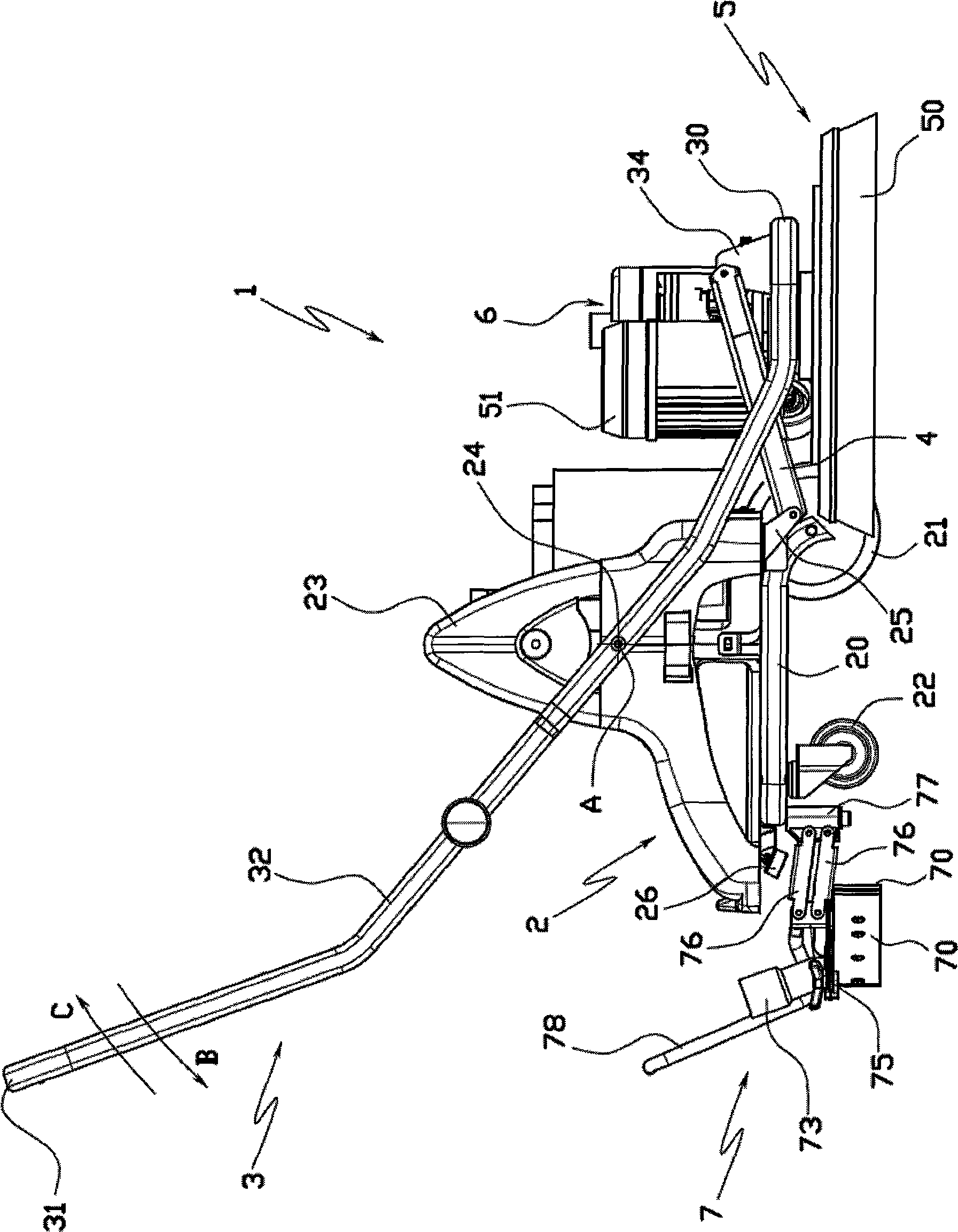
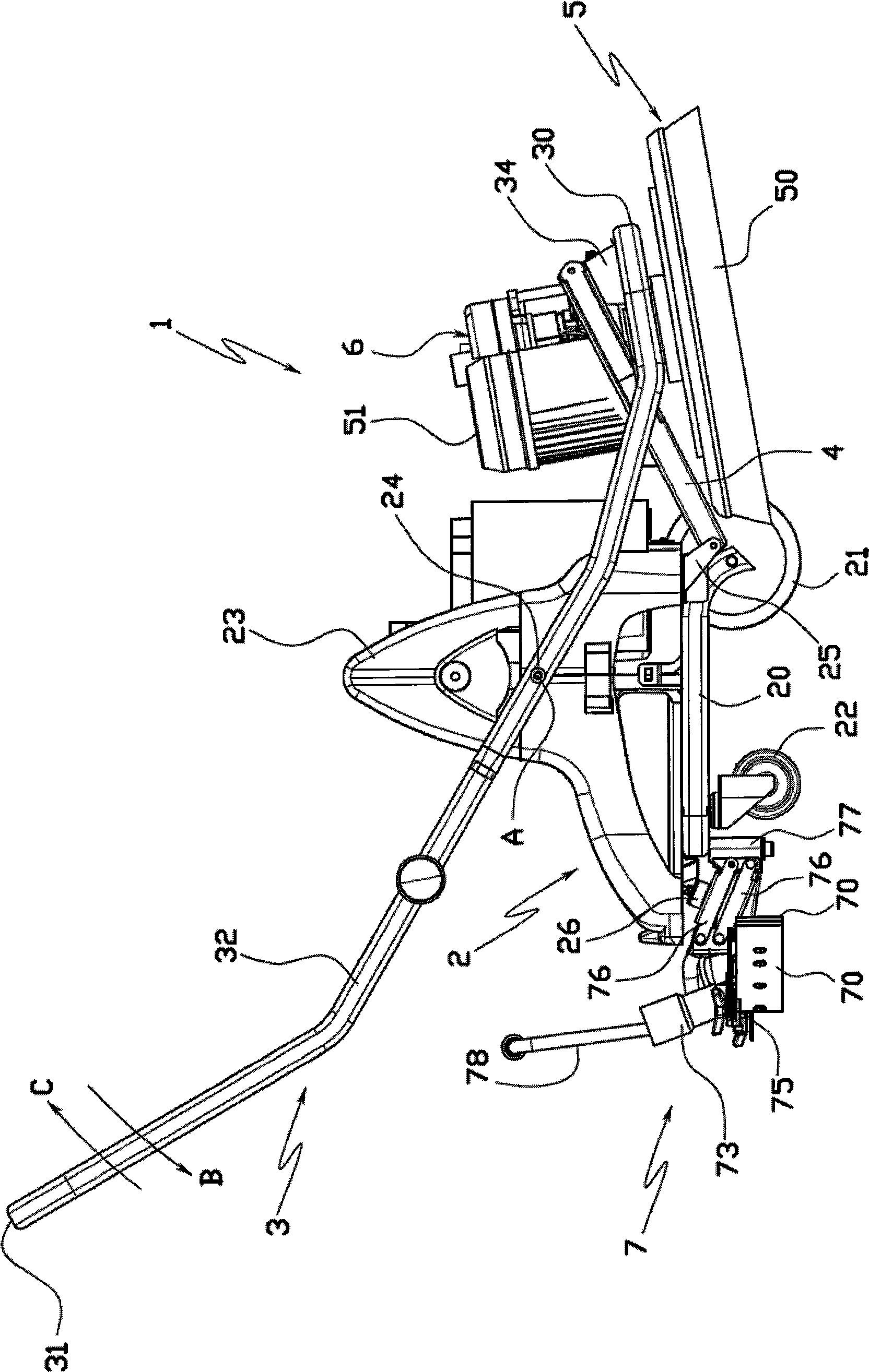
[0025] The floor cleaning machine 1 comprises a very compact, lightweight support trolley 2 having a horizontal base 20 and three support wheels including two coaxial, fixed axle front wheels 21 and a pivoting rear wheel 22 .

[0026] Two oppositely positioned, identically shaped convex side elements 23 are secured to the movable support trolley 2, laterally delimiting the loading space of said trolley 2, preferably made of plastic.

[0027] A rigid frame 3 , preferably made of sheet steel, is hinged to said side elements 23 .

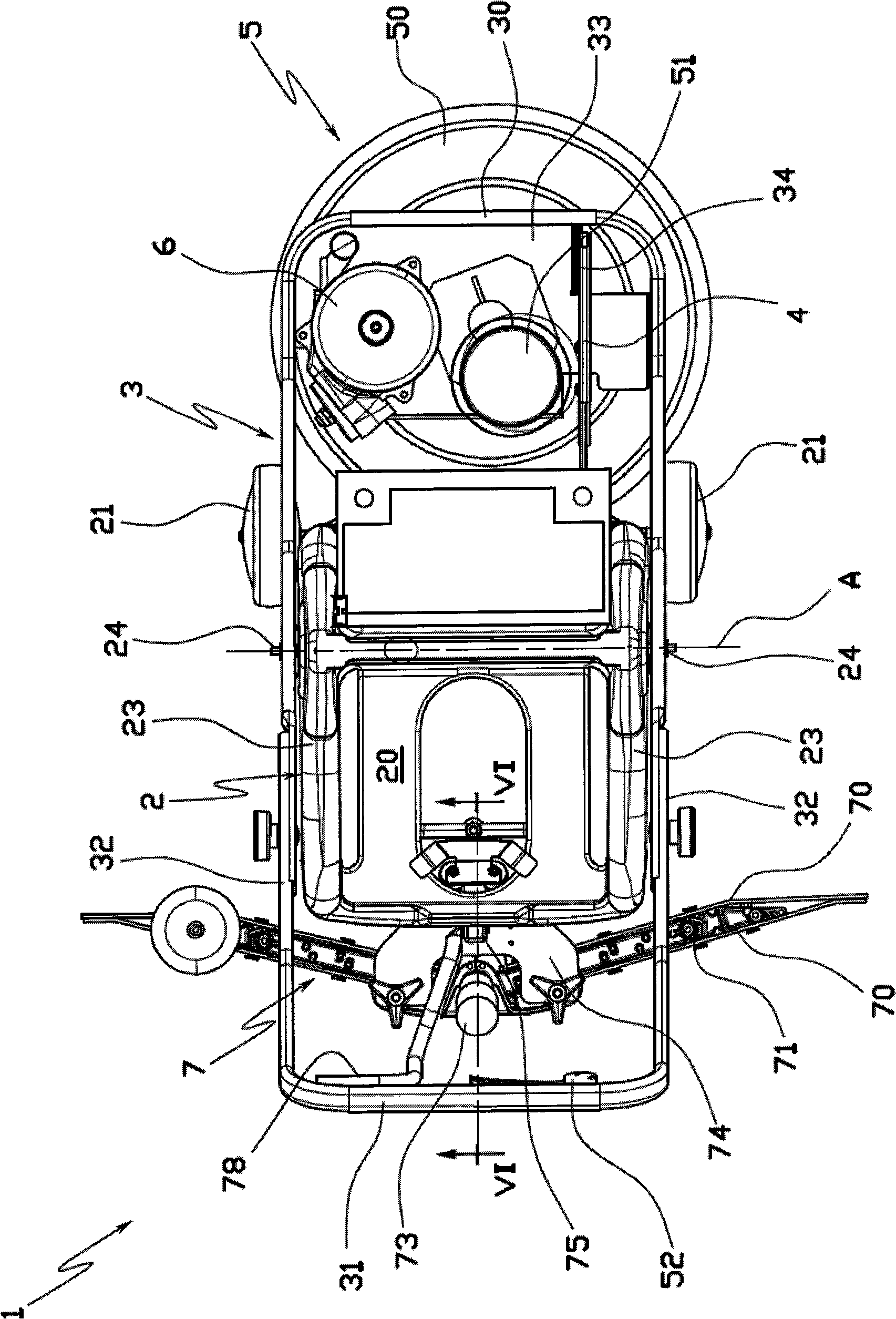
[0028] Such as figure 2 As shown, the frame 3 has rounded corners and two cross-bars, namely a front cross-bar 30 and a rear cross-bar 31 , which are connected together by two opposite longitudinal bars 32 of the same shape.

[0029] The rigid frame 3 is embedded on the outer surface of the side elements 23 of the mobile support trolley 2 and is articulated to said trolley 2 by means of two hinged connections 24 connecting the respective side element...


PUM


Abstract

A floor-cleaning machine comprises a support trolley (2), on which support trolley (2) at least a floor-cleaning group (7) is installed, which floor-cleaning group (7) is provided with at least a flexible blade (70) and is mobile between a work position, in which the flexible blade (70) is in contact with a floor, and a rest position, which is characterized in that the floor-cleaning machine comprises magnetic means (26) which adsorbs the floor-cleaning group (7) in the rest position.

Description

technical field [0001] The present invention relates to floor cleaning machines, in particular, to professional floor cleaning machines, which are mainly used for cleaning very large floors, such as in commercial and / or small industrial premises. Background technique [0002] Professional floor cleaning machines are usually divided into two types. The cleaning machines installed on the self-propelled vehicles driven by the operator are generally called "man on board" (man on board) cleaning machines, and the cleaning machines installed on the operator walk behind the machine. A cleaning machine on a trolley pushed by an operator is called a "walk-behind" cleaning machine. [0003] The present invention generally relates to walk-behind cleaning machines. [0004] As is well known, walk-behind floor cleaning machines include working assemblies for performing specific floor cleaning operations, these working assemblies include: one or more motorized rotating brushes for scrubb...

Claims


Application Information

Patent Timeline
Patent Type & Authority Applications(China)
IPC IPC(8): E01H1/08
CPCA47L11/2025A47L11/4016A47L11/4055A47L11/4027A47L11/305A47L11/4041A47L11/4061A47L11/4088A47L11/4083A47L11/4044
Inventor 弗朗西斯科·雷卡纳罗
Owner IP CLEANING
Why Eureka
Try Eureka