Method for discharging fuel collected container of tank vent system and fuel tank vent system

A technology of ventilation system and collecting container, which is applied in the field of fuel tank ventilation system and motor vehicle

Active Publication Date: 2013-02-20
AUDI AG
View PDF4 Cites 0 Cited by
  • Summary
  • Abstract
  • Description
  • Claims
  • Application Information

AI Technical Summary

Problems solved by technology

The disadvantage of this arrangement is that on the one hand (to) open additional paths for liquid fuel (liquid entrainment / carryover (LCO)) into the tank ventilation system and on the other hand additional drain valves are required

Method used


Image

  • Method for discharging fuel collected container of tank vent system and fuel tank vent system

Examples


Embodiment Construction

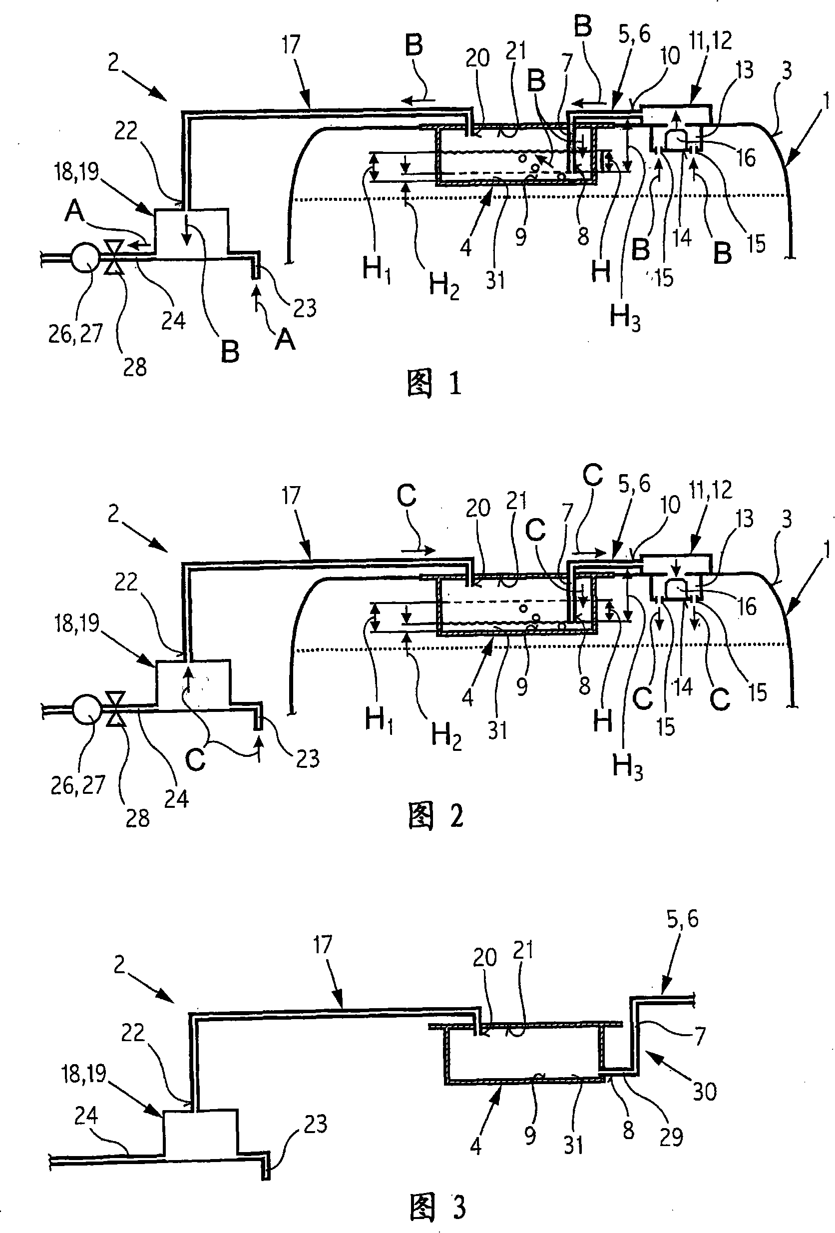
[0023] FIG. 1 shows a schematic diagram of a fuel tank 1 and a tank ventilation system 2 of an internal combustion engine (not shown) of a motor vehicle. The fuel tank ventilation system 2 has an associated fuel collecting container 4 in the upper region 3 of the fuel tank 1 . The fuel collecting container 4 is in flow communication with the fuel tank 1 via a ventilation line 5 . The ventilation duct 5 is designed as an L-shaped ventilation pipe 6, the downcomer 7 of which opens into the interior of the fuel collection container 4 from above and terminates at one end 8 in the bottom area near the bottom plate 9 of the fuel collection container 4 Inside. The other end 10 of the ventilation line 6 , which is opposite the one end 8 , is connected to a valve 12 designed as a float valve 11 for preventing liquid fuel from penetrating into the tank ventilation system 2 . The float valve 11 arranged in the upper region 3 of the tank 1 has a buoyancy chamber 13 which has an opening ...


PUM


Abstract

The method involves generating a low pressure in a tank (1) relative to the pressure in a fuel collecting vessel (4) of a tank deaerator (2) in a combustion engine of a motor vehicle. The low pressure is generated during a fresh air suction process for the regeneration of a hydrocarbon containment filter (18) of tank deaerator. Liquid fuel available in the fuel collecting vessel is sucked back through an exhaust assembly (5) in the tank. The liquid fuel is sucked back after the completion of fresh air suction process and based on the pressure ratio resulting from the air suction process. An independent claim is also included for a tank deaerator with a fuel collecting vessel for reserving liquid fuel.

Description

technical field [0001] The present invention relates to a method for emptying a fuel collection container of trapped liquid fuel (liquid fuel) of a fuel tank ventilation (exhaust) system / equipment, wherein the fuel collection container communicates with the fuel tank through a ventilation duct (vent passage), In particular for use in vehicles, preferably motor vehicles, with an internal combustion engine. [0002] Furthermore, the invention relates to a fuel tank ventilation system with a fuel collecting container retaining liquid fuel, which fuel collecting container communicates with the fuel tank via a ventilation line, in particular for use in a vehicle, preferably a motor vehicle, with an internal combustion engine. Background technique [0003] Methods for emptying a liquid fuel-entrapped fuel collection container of a fuel tank ventilation system and corresponding fuel tank systems are known. In these methods and systems, emptying is performed by flowing (recirculat...

Claims


Application Information

Patent Timeline
Patent Type & Authority Patents(China)
IPC IPC(8): B60K15/035
CPCF02M25/089F02M37/0082F02M37/20
Inventor H·哈根
Owner AUDI AG
Why Eureka
Try Eureka