Vacuum pump system and method for operating a vacuum pump system

A vacuum pump and catheter technology, applied in the direction of pumps, pump components, rotary piston pumps, etc., can solve problems such as high energy consumption, achieve energy saving, achieve the effect of pumping capacity, and high pumping capacity

Active Publication Date: 2018-02-16
レイボルドゲーエムベーハー
View PDF6 Cites 0 Cited by
  • Summary
  • Abstract
  • Description
  • Claims
  • Application Information

AI Technical Summary

Problems solved by technology

This results in a correspondingly high energy consumption

Method used


Image

  • Vacuum pump system and method for operating a vacuum pump system
  • Vacuum pump system and method for operating a vacuum pump system
  • Vacuum pump system and method for operating a vacuum pump system

Examples


Embodiment Construction

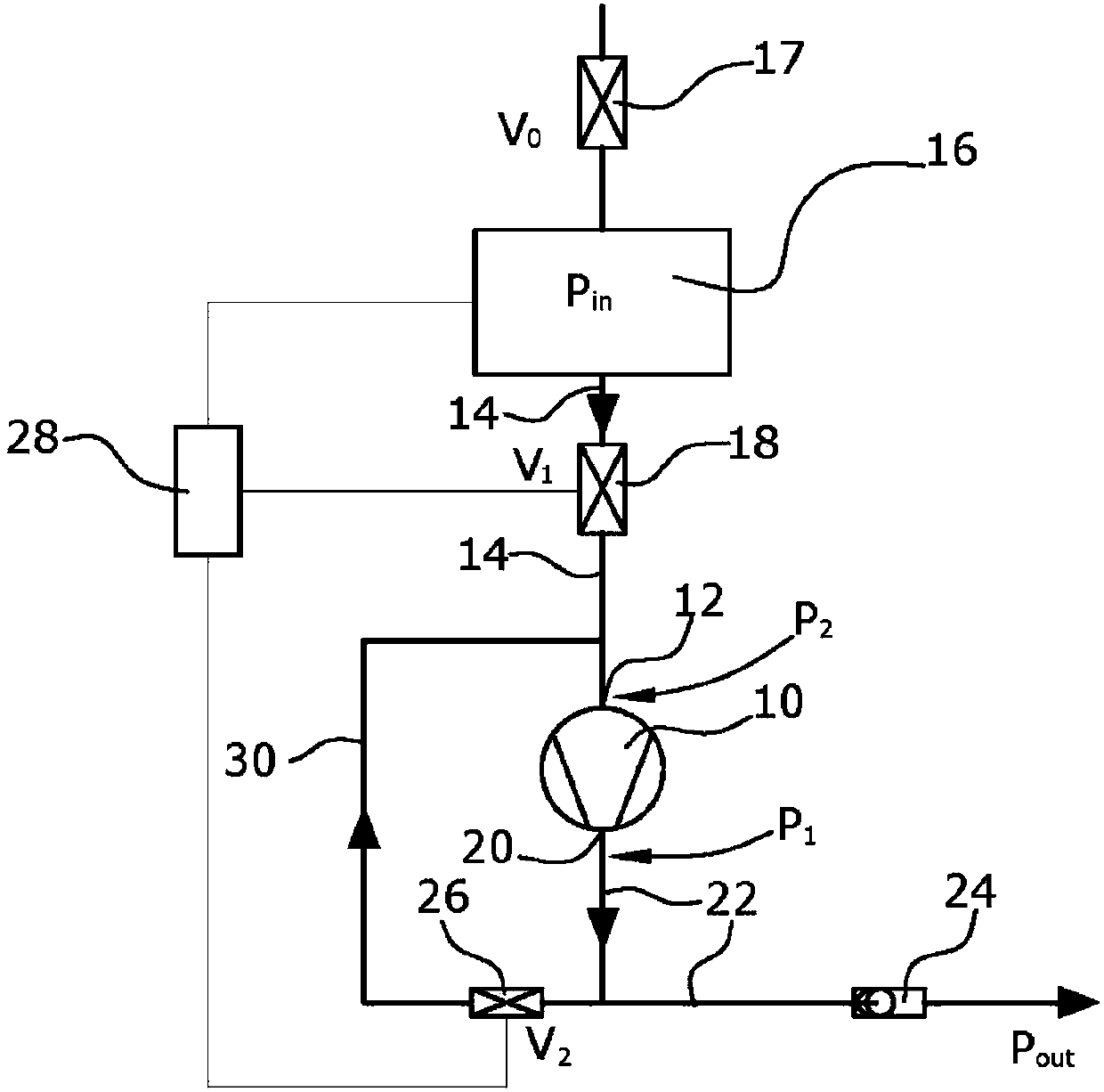
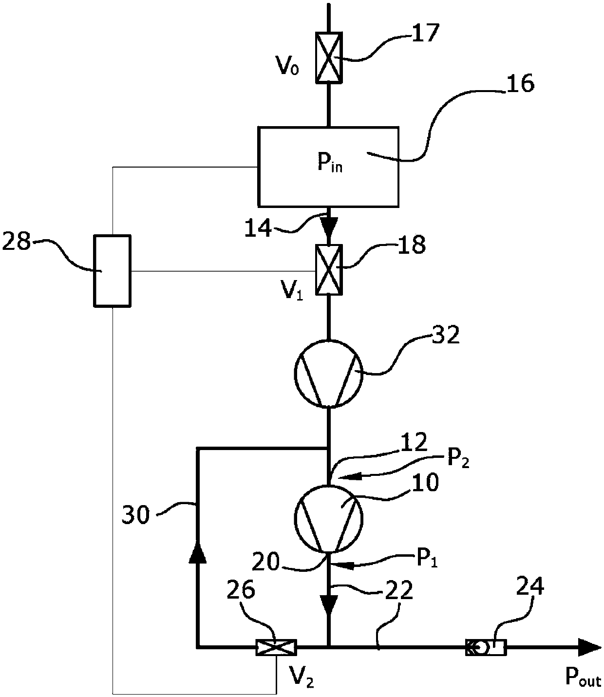
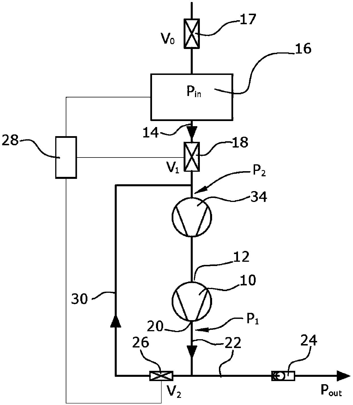
[0037] figure 1 The vacuum pump shown in includes a screw pump 10. The inlet 12 of the vacuum pump is connected via an inlet conduit 14 to a chamber, such as a lock chamber or process chamber 16 . Chamber 16 has a valve 17 (valve V 0 ) to close the import. Inlet valve 18 (valve V 1 ), specifically the controllable inlet valve is arranged in the inlet conduit 14 .

[0038] The outlet 20 of the vacuum pump 10 is connected to an outlet conduit 22 in which a check valve 24 is arranged. Outlet line 22 may be immediately connected to the atmosphere or to an exhaust system having a predetermined system pressure. The system pressure can be above or below atmospheric pressure.

[0039] Further, the outlet conduit 22 is connected to the inlet conduit 14 via a bypass conduit 30 . Bypass valve 26 (valve V 2 ) is in particular an electrically switchable bypass valve arranged in the bypass conduit 30 . Further, a control device 28 is provided, which is connected to at least the inl...


PUM


Abstract

The invention relates to a vacuum pump system comprising a vacuum pump (10), in particular in the form of a screw pump. The system is used to evacuate the chamber (16). When the desired set pressure in the chamber (16) is reached, the vacuum pump system can be operated in standby mode. To this end, the outlet conduit (22) is connected to the inlet conduit (30) via a bypass conduit (24). In standby mode, the inlet valve (18) is closed and the bypass valve (26) is opened so that the medium in the circuit can be delivered by the vacuum pump (10). As a result, the vacuum pump is maintained substantially at operating temperature.

Description

technical field [0001] The invention relates to a vacuum pump system and to a method for operating a vacuum pump system. Background technique [0002] Vacuum pumps and vacuum pump systems are frequently used to evacuate chambers in a short time. This is achieved by using dry compression vacuum pumps such as eg screw pumps, claw pumps or multi-stage Roots pumps. Oil-sealed vacuum pumps such as rotary vane pumps or rotary piston pumps may also be used. Frequently, multiple pumps are arranged in series and / or in parallel with each other, enabling pumping of large volumes of gas in short periods of time. [0003] Typical applications are eg lock chambers used in coating installations. The lock chamber must be pumped down from atmospheric pressure to delivery pressure in short intervals. Usually this is done in a period of from 20 seconds to 120 seconds to achieve a delivery pressure of between 0.1 mbar and 10 mbar. Thereafter, the valve arranged between the lock chamber and...

Claims


Application Information

Patent Timeline
Patent Type & Authority Patents(China)
IPC IPC(8): F04C28/06F04C25/02F04C28/02F04C28/08
CPCF04C28/06F04C18/16F04C25/02F04C28/02F04C28/08F04C2220/12
Inventor 克里斯蒂安·拜尔托马斯·德赖费特罗兰·穆勒丹尼尔·施奈登巴赫马克思·百利金德克·席勒德克·施特拉特曼
Owner レイボルドゲーエムベーハー
Why Eureka
Try Eureka