Air supply and exhaust system and air supply and exhaust method for a sterilizing dryer

A dryer and air supply fan technology, applied in the direction of dryers, drying, packaging and sterilization, etc., can solve the problems of equipment pressure fluctuations, equipment air volume changes, equipment adjustment difficulties, etc., to achieve simple and convenient adjustment, reduce The effect of differential pressure fluctuations

Active Publication Date: 2017-03-22
TRUKING TECH LTD
View PDF6 Cites 0 Cited by
  • Summary
  • Abstract
  • Description
  • Claims
  • Application Information

AI Technical Summary

Problems solved by technology

In the above technical solution, the air supply assembly and the exhaust assembly are directly connected to the oven assembly. Therefore, the air supply assembly and the exhaust assembly need to be properly adjusted considering the air volume required by the equipment. The air volume adjustment of the air supply assembly and the exhaust assembly is very simple. Difficult to control and difficult to adjust the equipment; at the same time, when the sterilizing dryer starts or stops running, the internal air volume of the equipment changes greatly, which can easily cause pressure fluctuations inside the equipment

Method used


Image

  • Air supply and exhaust system and air supply and exhaust method for a sterilizing dryer
  • Air supply and exhaust system and air supply and exhaust method for a sterilizing dryer
  • Air supply and exhaust system and air supply and exhaust method for a sterilizing dryer

Examples


Embodiment Construction

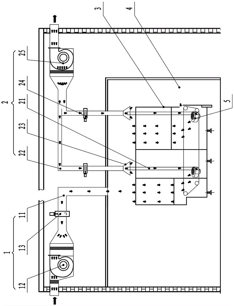
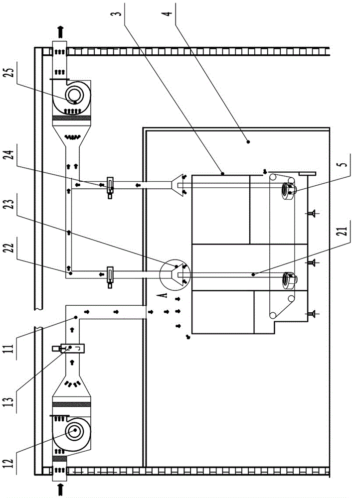
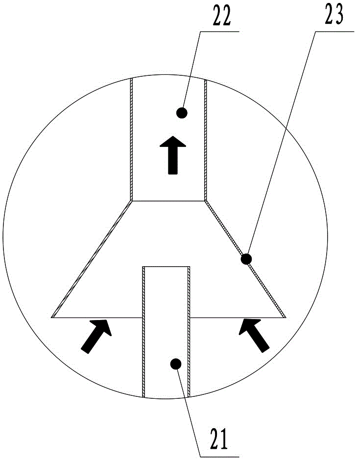
[0024] Such as Figure 1 to Figure 3 As shown, the air supply and exhaust system of the sterilization dryer in this embodiment includes an air supply assembly 1, an exhaust assembly 2, and a clean chamber 4. The sterilization dryer 3 is placed in the clean chamber 4, and the The air assembly 1 includes an air supply duct 11, the air supply duct 11 communicates with the clean chamber 4, the exhaust assembly 2 includes an exhaust duct 21 and an air introduction duct 22, the air introduction duct 22 communicates with the clean chamber 4, and the exhaust duct 21 The discharged gas directly enters the air-inducing duct 22 . Both the air supply duct 11 and the air induction duct 22 are in communication with the clean chamber 4. When the air volume of the air supply does not match the air volume required by the equipment, excess air can be sucked away through the air induction duct 22. Therefore, the air supply duct 11 is effectively avoided. When it is directly connected to the ste...


PUM


Abstract

The invention discloses an air blowing and exhausting system of a sterilizing and drying machine and an air blowing and exhausting method. The air blowing and exhausting system comprises an air blowing assembly and an air exhausting assembly, and further comprises a clean chamber in which the sterilizing and drying machine is arranged, wherein the air blowing assembly comprises an air blowing pipe; the air blowing pipe is communicated with the clean chamber; the air exhausting assembly comprises an air exhausting pipe and an air inducing pipe; the air inducing pipe is communicated with the clean chamber; air exhausted from the air exhausting pipe directly enters the air inducing pipe. The air blowing and exhausting method comprises the following steps: arranging the sterilizing and drying machine inside the clean chamber, and enabling the sterilizing and drying machine to be communicated with the clean chamber; blowing air into the clean chamber; in an air supplementing state or in a stopping state, exhausting surplus air in the clean chamber out of the clean chamber. The air blowing and exhausting system has the advantages of simple adjustment and reduction in pressure fluctuation inside the clean chamber.

Description

technical field [0001] The invention belongs to the field of food and pharmaceutical packaging machinery, and in particular relates to an air supply and exhaust system and an air supply and exhaust method for a sterilization dryer. Background technique [0002] The existing sterilizing dryer is placed in the D-level clean room, and its outlet port is connected with the B-level clean room. The B-level clean room and the D-level clean room need a pressure gradient greater than 10Pa. When it is closed, a large amount of air in the D-class clean room absorbed by it will not be discharged, and the pressure difference gradient between the D-class clean room and the B-class clean room will fluctuate greatly. In order to reduce the fluctuation of pressure difference, it is necessary to configure independent air supply components and exhaust components for the tunnel sterilization dryer. [0003] Chinese invention patent 201110406020.5 discloses an air supply and exhaust system for ...

Claims


Application Information

Patent Timeline
Patent Type & Authority Patents(China)
IPC IPC(8): B65B55/00B65B55/02
CPCB65B55/00B65B55/02F26B21/00
Inventor 易波蔡大宇
Owner TRUKING TECH LTD
Why Eureka
Try Eureka