Pressure limiting valve of aero-engine oil pump

A technology of aero-engine and pressure-limiting valve, which is applied in the direction of engine lubrication, engine components, lubricating oil control valve, etc., to achieve the effect of smooth adjustment and avoid adjustment difficulties

Active Publication Date: 2022-06-28
芜湖钻石航空发动机有限公司
View PDF6 Cites 0 Cited by
  • Summary
  • Abstract
  • Description
  • Claims
  • Application Information

AI Technical Summary

Problems solved by technology

Traditional automobile engines seldom do verification of limit oil pressure conditions, so there is no design structure for controlling oil pressure by changing the structure of the pressure limiting valve

Method used


Image

  • Pressure limiting valve of aero-engine oil pump
  • Pressure limiting valve of aero-engine oil pump
  • Pressure limiting valve of aero-engine oil pump

Examples


Embodiment 1

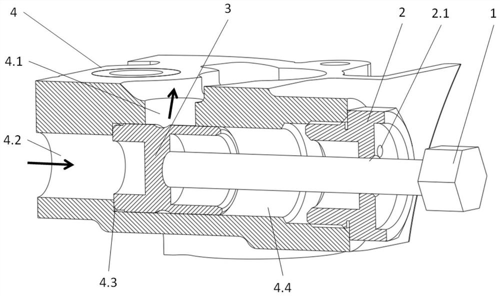
[0020] Example 1, as Figure 1-2 As shown, the present invention provides a technical solution: a pressure limiting valve for an aero-engine oil pump, comprising a rotatable screw 1, a screw plug 2, a displacement valve core 3 and an oil pump housing 4, the A screw plug 2 is provided inside, and the inside of the screw plug 2 is provided with an oil pressure adjustment mechanism for manually adjusting the pressure of the oil pump pressure limiting valve. The oil pressure adjustment mechanism includes a rotatable screw 1 and a displacement valve core 3. A rotatable screw 1 is provided through the fine thread, and the rotatable screw 1 and the screw plug 2 are in a threaded connection relationship. Displace the valve core 3, and the outer wall of the displacement valve core 3 matches the outer wall of the installation cavity 4.4 of the pressure limiting valve structure, and the outer wall of the displacement valve core 3 corresponds to the outer wall of the installation boss 4.3...

Embodiment 2

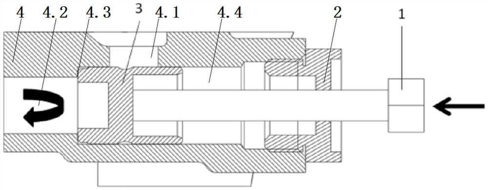
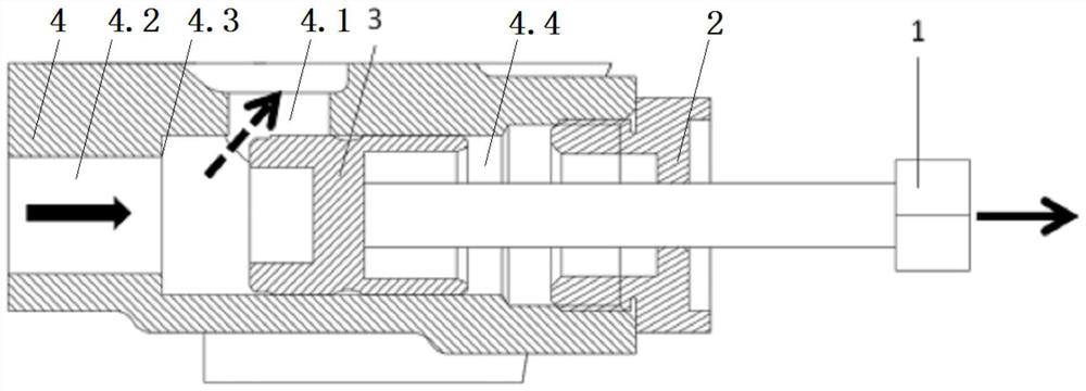
[0021] Example 2, as Figure 1-3 As shown, the present invention provides a technical solution: a pressure limiting valve for an aero-engine oil pump, comprising an oil pump housing 4 and an installation cavity 4.4 of the pressure limiting valve structure, and a middle position inside the oil pump housing 4 is opened The installation cavity 4.4 of the pressure-limiting valve structure, and the side of the installation cavity 4.4 of the pressure-limiting valve structure away from the screw plug 2 is provided with an oil pump high pressure feedback oil cavity 4.2, and the side wall of the screw plug 2 is provided with a pressure-limiting valve structure. Install the exhaust component of the air pressure in the cavity 4.4. The exhaust component includes an exhaust hole 2.1. The side wall of the screw plug 2 is provided with an exhaust hole 2.1 for connecting with the installation cavity 4.4 of the pressure limiting valve structure, and 2.2 is far away from One side of the install...


PUM


Abstract

The invention discloses a pressure-limiting valve of an aero-engine oil pump, which comprises a rotatable screw rod, a screw plug, a shifting valve core and an oil pump shell, the screw plug is arranged in the oil pump shell, and a control mechanism for manually adjusting the pressure of the pressure-limiting valve of the oil pump is arranged in the screw plug. A mounting cavity of the pressure limiting valve structure is formed in the middle position in the oil pump shell, an oil pump high-pressure feedback oil cavity is formed in the side, away from the screw plug, of the mounting cavity of the pressure limiting valve structure, and an exhaust assembly used for adjusting the air pressure in the mounting cavity of the pressure limiting valve structure is arranged on the side wall of the screw plug. An oil pump pressure-limiting valve oil drainage cavity located above the installation cavity of the pressure-limiting valve structure is formed in the top end of the oil pump shell. By the adoption of the technical scheme, the rotatable screw rod is rotated to be meshed with the fine thread groove in the screw plug, so that the rotatable screw rod drives the shifting valve element to be arranged in the mounting cavity of the pressure limiting valve structure, and air pressure adjustment of high-pressure engine oil in the engine oil pump shell is facilitated.

Description

technical field [0001] The invention belongs to the field of aero-engine oil pump devices, and more particularly, the invention relates to a pressure limiting valve of an aero-engine oil pump. Background technique [0002] The oil pump is a key part of the engine, and its main function is to provide sufficient pressure and appropriate flow to the lubrication system to achieve pressure oil lubrication. For a fixed displacement oil pump, generally with the increase of the engine speed, the outlet flow of the oil pump also increases, but at a certain speed and temperature of the engine, the flow required for each lubrication is basically fixed, and the oil pump Excessive flow output will cause the oil pressure of the engine lubrication system to be too high, so the fixed displacement oil pump generally has a pressure-limiting valve structure. [0003] However, in the limit oil pressure verification test of the aero-engine, the oil pump needs to be adjusted to the minimum oil p...

Claims


Application Information

Patent Timeline
Patent Type & Authority Applications(China)
IPC IPC(8): F16N23/00F16K1/04F16K24/04
CPCF16N23/00F16K1/04F16K24/04Y02T50/40
Inventor 于萍汤绪雯岑杰胡崇波郑君
Owner 芜湖钻石航空发动机有限公司
Why Eureka
Try Eureka