Two-phase flow cooling device for IGBT

A cooling device and phase flow technology, applied in electrical components, electrical solid devices, circuits, etc., can solve the problems of unstable temperature control, prone to failure, poor heat dissipation efficiency, etc., to improve the effect of buffering and release, easy to assemble and adjustment, the effect of improving work stability

Pending Publication Date: 2021-04-13
上海分分充新能源技术有限公司
View PDF0 Cites 1 Cited by
  • Summary
  • Abstract
  • Description
  • Claims
  • Application Information

AI Technical Summary

Problems solved by technology

Its main disadvantages are: poor heat dissipation efficiency, unstable temperature control, greatly affected by the space environment and air temperature, and the air cooling device occupies a large volume overall, the system is not airtight, and has a great impact on the life of electronic components in the system
Its main disadvantages are: controlling the temperature of the chip requires a large flow of refrigerant, which leads to large flow resistance and high pressure of the entire system, high requirements for the power of the system pump, and high requirements for the airtightness of the system, which is prone to failure. Poor stability; at the same time, water or ethylene glycol aqueous solution is generally used as the coolant, which may cause scaling and corrosion risks for a long time

Method used


Image

  • Two-phase flow cooling device for IGBT
  • Two-phase flow cooling device for IGBT
  • Two-phase flow cooling device for IGBT

Examples


Embodiment 1

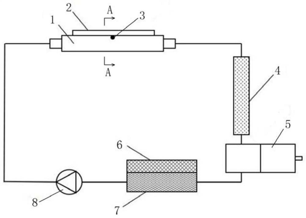
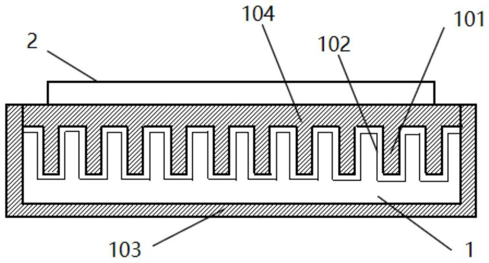
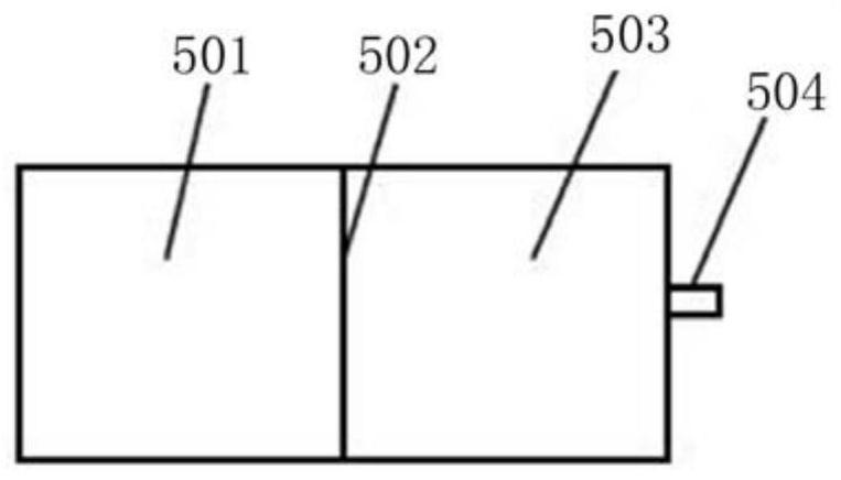
[0031] Such as figure 1 As shown, this embodiment provides a two-phase flow cooling device for IGBT, which is aimed at the IGBT in a certain charging pile. The two-phase flow cooling device includes a heat exchange cold plate module 1 , a mixed flow pipe 4 , a liquid storage buffer tank 5 , a radiator 7 and a power pump 8 . The heat exchange cold plate module 1, the mixed flow pipe 4, the liquid storage buffer tank 5 and the radiator 7 are sequentially connected in an annular manner to form a cooling circulation flow channel, and the power pump 8 is connected to the cooling circulation flow channel, which is specifically arranged in the heat exchange cold plate module 1 and radiator 7. The IGBT2 is welded on the heat exchange cold plate module 1 .

[0032] The cooling cycle process of this example is: the liquid refrigerant with a certain degree of supercooling is transferred to the heat exchange cold plate module 1 through the power pump 8, and is partially vaporized in the...

Embodiment 2

[0043] Such as Figure 4 As shown, the difference between this embodiment and Embodiment 1 is that there are multiple heat exchange cold plate modules 1 arranged side by side, and the two ends of the multiple heat exchange cold plate modules 1 are connected to the cooling circulation flow through the bus bar 9 Road, preferably four in this embodiment.


PUM


Abstract

The invention relates to a two-phase flow cooling device for IGBT. The device comprises a heat exchange cold plate module, a flow mixing pipe, a liquid storage buffer tank, a radiator and a power pump, the heat exchange cold plate module, the flow mixing pipe, the liquid storage buffer tank and the radiator are sequentially and annularly connected to form a cooling circulation flow channel, and the power pump is connected into the cooling circulation flow channel; and the heat exchange cold plate module comprises a hollow shell, the two ends of the shell are connected into the cooling circulation flow channels, a heat exchange panel is arranged on one side face of the shell, IGBTs are welded to the outer side face of the heat exchange panel, heat exchange fins are arranged on the inner side face of the heat exchange panel, and an intensified boiling layer is arranged on each heat exchange fin. Compared with like devices in the prior art, the cooling device has the advantages that efficient heat dissipation of small-flow refrigerants is achieved, the power requirement and the overall leakproofness requirement of the cooling device for the power pump are lowered, and the working stability is improved.

Description

technical field [0001] The invention relates to the field of IGBT heat dissipation, in particular to a two-phase flow cooling device for IGBT. Background technique [0002] At present, the cooling methods for high-power IGBT chips on the market mainly adopt forced air cooling and indirect liquid cooling technologies. [0003] The main way of air cooling is the forced convection heat transfer of fans and heat sinks. Its main disadvantages are: poor heat dissipation efficiency, unstable temperature control, greatly affected by the space environment and temperature, and the air cooling device occupies a large volume overall, the system is not airtight, and has a great impact on the life of the electronic components of the system. [0004] The indirect liquid cooling technology uses a liquid cooling plate for cooling. The IGBT chip is pasted on the liquid cooling plate through thermal paste, thermal adhesive, etc., and then the liquid cooling plate is connected to an external r...

Claims


Application Information

Patent Timeline
Patent Type & Authority Applications(China)
IPC IPC(8): H01L23/367H01L23/44H01L23/467
CPCH01L23/3672H01L23/445H01L23/467
Inventor 李萍
Owner 上海分分充新能源技术有限公司
Why Eureka
Try Eureka