Self-circulating submerged jet phase-change liquid-cooling heat dissipation device inside the blade server shell

A blade server and heat dissipation device technology, which is applied in the direction of using liquid cooling for modification, cooling/ventilation/heating modification, and instrumentation, etc. It can solve the problem of preventing direct contact between liquid refrigerant and the surface of the heat source, unable to maintain a constant temperature of the heating element, and unable to replace it efficiently Heat and other problems, to achieve the effect of heat dissipation, heat exchange efficiency improvement, and increase of refrigerant disturbance

Active Publication Date: 2022-06-21
SUGON DATAENERGYBEIJING CO LTD
View PDF6 Cites 0 Cited by
  • Summary
  • Abstract
  • Description
  • Claims
  • Application Information

AI Technical Summary

Problems solved by technology

[0004] At present, the heat flux density of supercomputer heating elements has been further increased, and the arrangement of heating elements is becoming more and more dense. Since the boiling bubbles hinder the direct contact between the liquid refrigerant and the surface of the heat source, it is impossible to transfer heat efficiently.
Bubbles generated solely by immersion refrigerant boiling cannot take away more heat, and cannot maintain the temperature of the heating element below the high temperature upper limit of the heating element, which may cause the heating element to burn out

Method used


Image

  • Self-circulating submerged jet phase-change liquid-cooling heat dissipation device inside the blade server shell
  • Self-circulating submerged jet phase-change liquid-cooling heat dissipation device inside the blade server shell
  • Self-circulating submerged jet phase-change liquid-cooling heat dissipation device inside the blade server shell

Examples


Embodiment Construction

[0025] In order to more clearly understand the above objects, features and advantages of the present application, the present application will be further described in detail below with reference to the accompanying drawings and specific embodiments. It should be noted that the embodiments of the present application and the features of the embodiments may be combined with each other unless there is conflict.

[0026] In the following description, many specific details are set forth to facilitate a full understanding of the present application. However, the present application can also be implemented in other ways different from those described herein. Therefore, the protection scope of the present application is not subject to the following disclosure. Restrictions to specific embodiments.

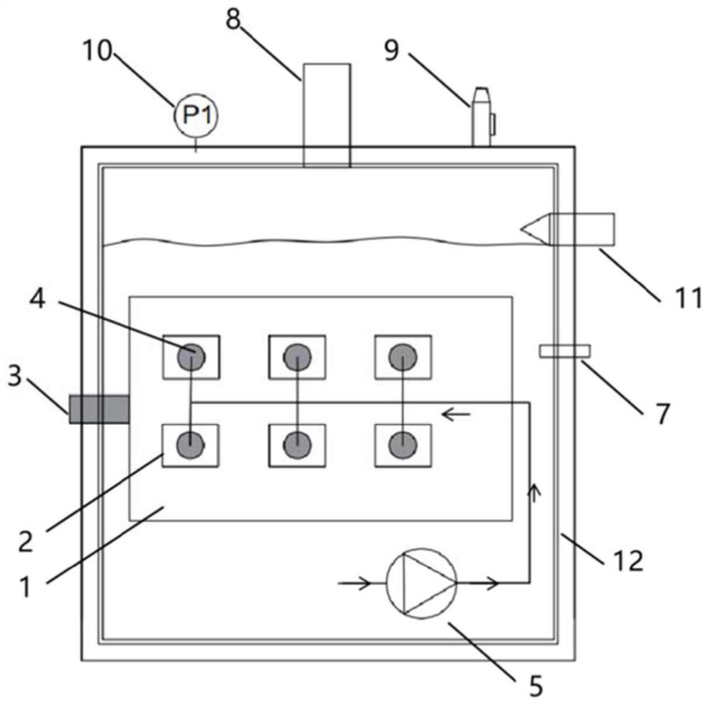
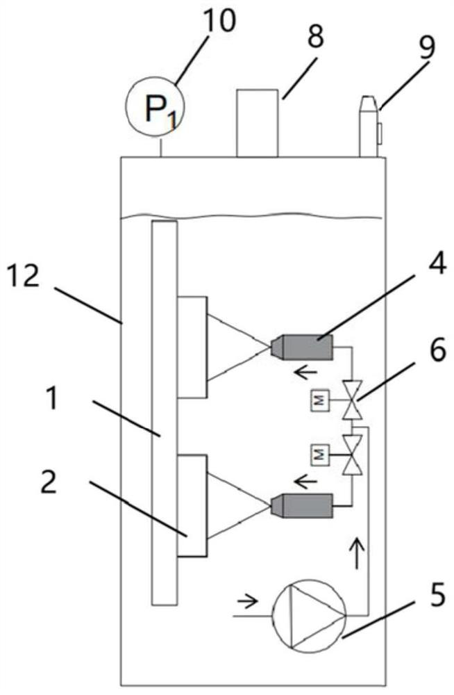
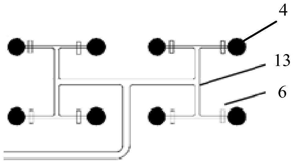
[0027] like figure 1 As shown in the figure, this embodiment provides a self-circulating submerged jet phase change liquid-cooling heat dissipation device inside the blade server shell. Th...


PUM


Abstract

This application discloses a self-circulating submerged jet phase-change liquid-cooled heat dissipation device inside the blade server shell. The liquid-cooled heat dissipation device includes: a refrigerant delivery device is arranged at the bottom of the cavity, connected to the liquid inlet end of the submerged jet device, and is used to turn the cavity The liquid refrigerant at the bottom of the body is transported to the submerged jet device; the submerged jet device is fixed on the side wall of the cavity and installed on the opposite side of the heating element. The side wall of the submerged jet device is provided with multiple upwardly inclined jet nozzles, and multiple jets The nozzles are respectively connected to a plurality of flow channel branches that are divided step by step in the knife shell flow channel. The knife shell flow channel is connected to the refrigerant delivery device. The liquid refrigerant ejected from the jet nozzle hits the heating element, and the gap between the jet nozzle hole and the heating element The spacing is a preset multiple of the diameter of the jet orifice. Through the technical solution in this application, the liquid refrigerant that has not undergone phase change in the blade housing is directly sprayed onto the heating element through the jet nozzle, taking away the heat generated by the heating element, and improving the heat dissipation performance of the liquid-cooled server.

Description

technical field [0001] The present application relates to the technical field of submerged liquid cooling servers, and in particular, to a submerged jet phase change liquid cooling device inside a blade server shell. Background technique [0002] The heat dissipation principle of the liquid-cooled server is to use the working fluid as an intermediate heat transfer medium, and transfer the heat from the hot zone to the distant place for cooling. Since the specific heat of liquid is much larger than that of air, and the heat dissipation rate is much higher than that of air, the cooling efficiency is much higher than that of air cooling. [0003] The traditional immersion liquid-cooled server submerges the server motherboard in the server blade housing with liquid refrigerant. During the data processing of the server, the heating element on the motherboard heats up. When the temperature of the heating element is higher than the boiling point of the refrigerant When the liquid ...

Claims


Application Information

Patent Timeline
Patent Type & Authority Patents(China)
IPC IPC(8): G06F1/20H05K7/20
CPCG06F1/20H05K7/203H05K7/20309
Inventor 默蓬勃沈卫东伊波力郭双江
Owner SUGON DATAENERGYBEIJING CO LTD
Why Eureka
Try Eureka