
Method of reducing the aerodynamic noise generated by an aircraft landing gear

A landing device, aerodynamic technology, applied to aircraft parts, transportation and packaging, landing gear, etc., can solve problems such as increased weight of structural components

Inactive Publication Date: 2008-10-08
MESSIER DOWTY
View PDF3 Cites 10 Cited by
  • Summary
  • Abstract
  • Description
  • Claims
  • Application Information

AI Technical Summary

Problems solved by technology

While this is effective for reducing noise, this results in a significant increase in the weight of the structural components and the technique is not suitable for large members such as side struts, leg struts, etc.

Method used


Image

  • Method of reducing the aerodynamic noise generated by an aircraft landing gear
  • Method of reducing the aerodynamic noise generated by an aircraft landing gear

Examples


Embodiment Construction

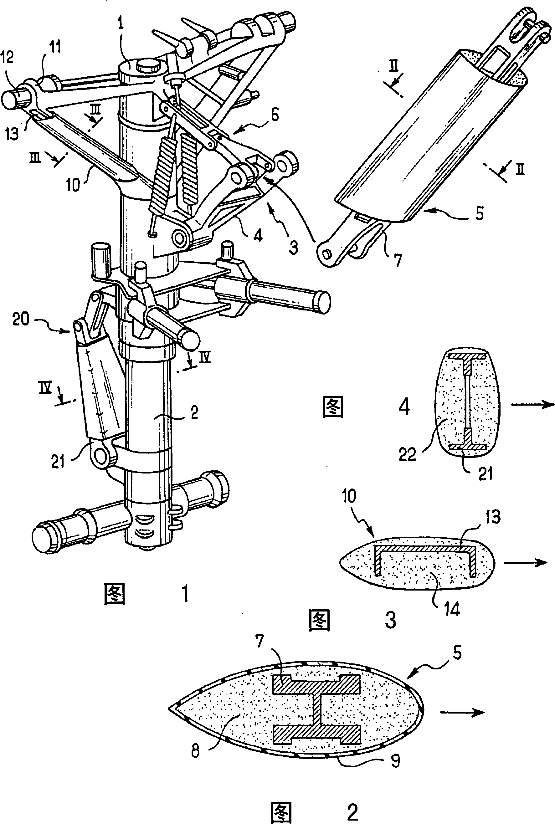
[0017] Referring to FIG. 1 , the illustrated landing device includes a strut 1 within which a rod 2 is mountable to slide telescopically. The landing gear is held in the deployed position by a bracket 3 which, as shown in this figure, comprises two arms articulated together, a bottom arm 4 articulated to the strut 1 and a top arm 5 articulated to the aircraft. Arms 4 and 5 are kept aligned by a stabilization mechanism 6 .

[0018] A first application of the invention concerns the top arm 5 of the carriage. As shown in Figure 2, it includes a structural part 7 of metal support, the main part of which has an "I"-shaped section, and the flange part of the "I" shape itself is recessed. The structural part therefore includes multiple hollows and cavities which may generate noise. According to the invention, the top arm 5 is coated with a lightweight material 8, in particular high-density polyurethane foam, to give the top arm 5 a smooth and aerodynamic shape. The entire shape it...


PUM


Abstract

The present invention relates to a method of reducing the noise generated when an aircraft landing of flying device is spread, the method includes at least one part (7, 13, 21) of the landing device is coated with materials (8, 14, 22) whose density is lower than that of elements, thereby the part is suitable for the shape of air mechanics of flowing gaseous current around.

Description

technical field [0001] The present invention relates to a method of reducing aerodynamic noise generated by aircraft landing gear. Background technique [0002] It is well known that during the landing process, the aerodynamic noise generated by the aircraft is mainly generated by the deployment of the landing gear of the aircraft. [0003] It has been proposed to place fairings onto the landing gear to deflect the airflow around parts that tend to generate noise, such as cavities. Such fairings can then be used as deflectors and they can be made of metal or composite materials. [0004] These rectifiers create various problems. First of all, it is appropriate to provide a number of attachment points for fixing the fairing on the components of the landing gear. In addition, these fairings must be coordinated with the motions involved in raising the landing gear and are complex to implement. Finally, these fairings add weight to the landing gear. [0005] These straighte...

Claims


Application Information

Patent Timeline
Patent Type & Authority Applications(China)
IPC IPC(8): B64C25/16
CPCB64C25/02B64C2025/003Y10T428/24992B64C25/14B64C25/001
Inventor C·瑟瑞Y·高格
Owner MESSIER DOWTY
Learn More