Floor plastic rubber lock catch convenient for connecting and positioning

A plastic and flooring technology, which is applied in the direction of floors, buildings, building structures, etc., can solve the problems of panel deformation, processing difficulties, poor elasticity, etc., and achieve the effect of reducing maintenance and expanding the use function

Active Publication Date: 2008-10-08
罗生权
View PDF0 Cites 14 Cited by
  • Summary
  • Abstract
  • Description
  • Claims
  • Application Information

AI Technical Summary

Problems solved by technology

The disadvantages of continuous plastic locks are poor elasticity and difficult processing. After the solid wood substrate is injected and cooled during production, the plastic condensation shrinks and the board surface is deformed; the intermittent plastic positioning lock floor solves the problem of plastic condensation shrinkage after injection molding. The board surface is deformed, but when they are assembled, the two floors must have a certain angle, and then apply downward pressure to deform the lower half of the tongue and groove and then snap into the tongue and groove of the floor, so that the plastic connection buckle is relatively large in plastic shrinkage , Assembled under the condition of low temperature and high brittleness, the plastic connecting buckle will break, which increases the difficulty of production and the difficulty of environmental requirements from the production process
In addition, the plastic lock floor has left and right points, which is inconvenient for production and assembly

Method used


Image

  • Floor plastic rubber lock catch convenient for connecting and positioning
  • Floor plastic rubber lock catch convenient for connecting and positioning
  • Floor plastic rubber lock catch convenient for connecting and positioning

Examples


Embodiment Construction

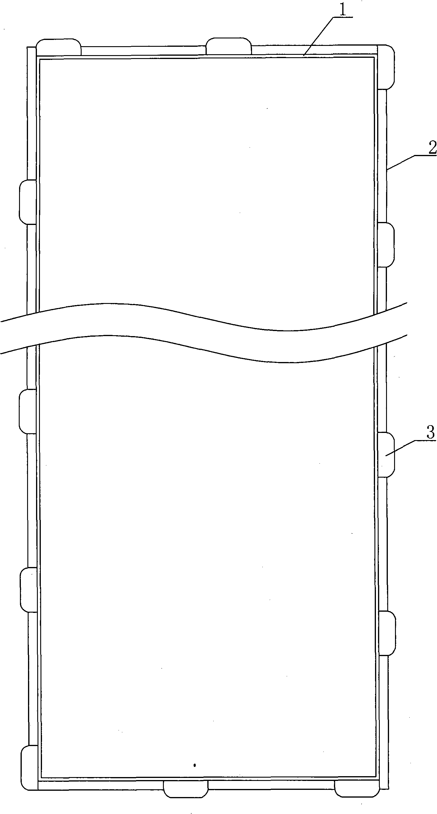
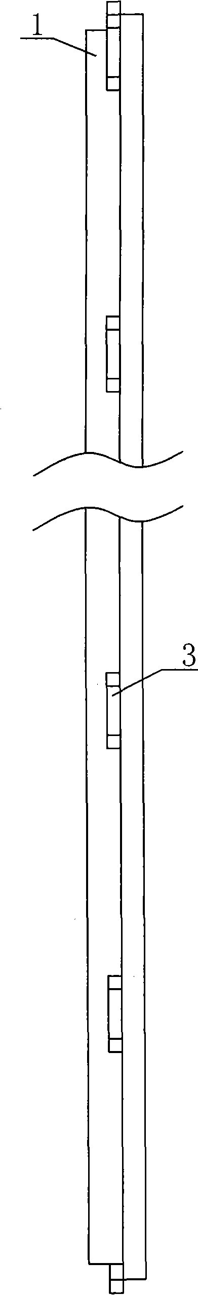
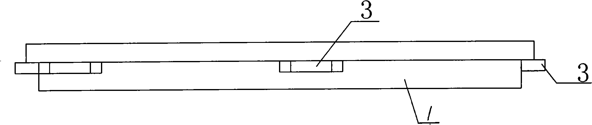
[0051] A floor plastic lock that is convenient for connection and positioning, such asfigure 1 , figure 2 , image 3 , Figure 4 In the shown embodiment 1, a plastic frame 1 is arranged on the periphery of the wooden floor or the fiber plywood floor, and stepped guide rails 2 shrinking inward are respectively arranged on the lower part of the outer surface of the plastic frame 1. On the stepped guide rails 2, respectively, The plastic sliders 3 whose outer ends protrude from the guide rail surface are uniformly arranged to match the guide rail surface of the corresponding assembled floor frame ladder guide rail 2. When assembling, the plastic slider 3 slides along the guide rail 2 to make the plastic slider and the assembled floor ladder guide rail. Matching positioning of the plastic slider. Figure 4 , Figure 5 , Image 6 , Figure 7 In the shown embodiment 2, plastic sliders 3 whose outer ends protrude from the surface of the guide rail are evenly distributed on the ...


PUM


Abstract

The invention relates to the improvement of mortice structure of wood floor and fiber glued floor, and the improvement of assembly method of wood floor and fiber glued floor, in particular to floor plastic fastener which is convenient for connecting and positioning. The improvement of the invention includes that plastic frame is arranged at the periphery of wood floor or fiber glued floor; the lower part of the external side of the plastic frame is respectively provided with a step guide which is capable of drawing back; the step guides are respectively and evenly provided with a plastic slide block, the external side of which extends out of the guide surface, and the plastic slide block, the external side of which extends out of the guide surface, matches with the step guide surface corresponding to the frame of the assembly floor; while assembling, the plastic slide block sliding along guide surface causes the plastic slide block and the plastic slide block to match with each other and to be located. The mortice structure of the invention changes the fastener structure and assembly method of the existing floor, causing no squeezing of the surface decoration layer of floor edge and no edge collapsing of the decoration layer while assembling, being able to adjust the size of the clearance between floors; the fastener of the floor need not differentiate with left and right, and thus free assembly in any end can be done while disassembling, which is convenient for production and assembly; in addition, the plastic fastener has high intensity, saves material and has low cost.

Description

technical field [0001] The invention relates to the improvement of the tenon and groove structure of the wooden floor and the fiber glued floor and the improvement of the assembling method of the wooden floor and the fiber glued floor, in particular to the floor plastic lock which is convenient for connection and positioning. Background technique [0002] Traditional wood flooring and fiber-glued flooring are assembled around and at the bottom of the floor into wooden tenon-joint flooring, wooden flat-joint flooring, wooden lock-lock flooring, and wooden tenon-joint mosaic floors with aluminum wire and glued paper or glued net joints Floor, the wooden floor and fiber glued floor processed by this method not only waste wood and reduce the floor area, but also require a large investment in processing machinery and equipment, requiring high mechanical precision, difficult to debug tools and equipment maintenance, and the processed floor is not high in precision. The assembly of...

Claims


Application Information

Patent Timeline
Patent Type & Authority Applications(China)
IPC IPC(8): E04F15/02
CPCE04F15/02E04F2201/0123E04F2201/095
Inventor 罗生权
Owner 罗生权
Why Eureka
Try Eureka