

Fuel purifying economizer
A fuel economizer and fuel technology, which is applied in machine/engine, combustion air/combustion-air treatment, engine components, etc., can solve the problems of lack of promotion and application, purification, and fuel-saving effect is not obvious, and achieve sufficient combustion. Effect
Inactive Publication Date: 2008-10-08
乔永汉
View PDF0 Cites 7 Cited by
- Summary
- Abstract
- Description
- Claims
- Application Information
AI Technical Summary
Problems solved by technology
The fuel oil purifying and fuel-saving device in the prior art has insignificant purification and fuel-saving effects, and has not been popularized and applied in the market due to the inconspicuous effects of purification and fuel-saving.
Method used
View moreImage
Smart ImageViewing Examples

Examples
Embodiment Construction
Login to View More PUM
 Abstract
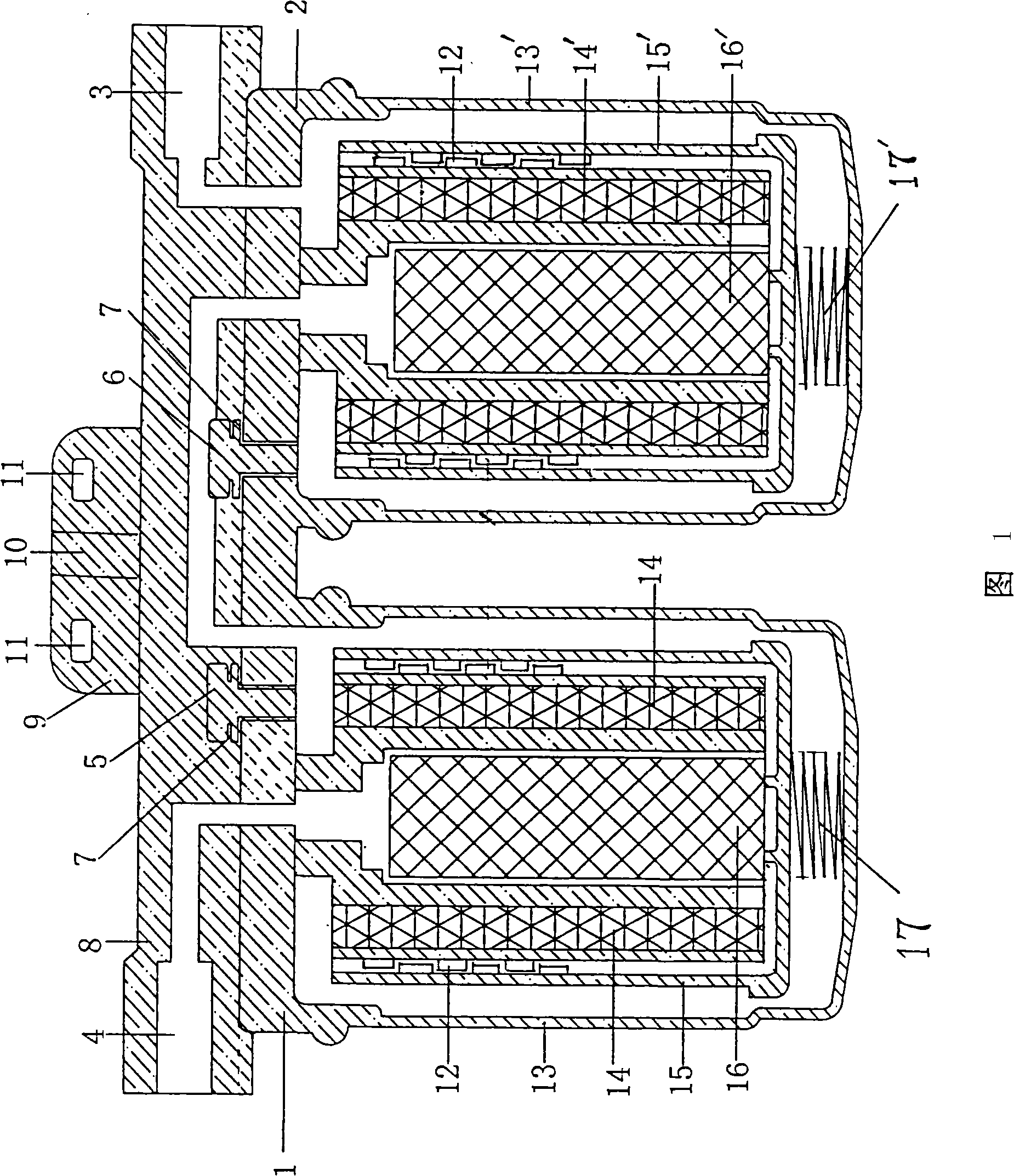
The invention relates to a fuel purification economizer. The fuel economizer of the invention is divided into a left single cylinder and a right single cylinder, wherein, the left single cylinder is formed in a way that a left upper cover is connected with a shell of a left lower cylinder while the right single cylinder is formed in a way that a right upper cover is connected with a right lower cylinder. The left upper cover is provided with a left air exhaust screw while the right upper cover is provided with a right air exhaust screw; the edge of the right upper cover is provided with a fuel inlet hole while the edge of the left upper cover is provided with a fuel outlet hole; a left oil-resistant plastic inner core fixing body and a right oil-resistant plastic inner core fixing body both take the shape of a cylinder; six straight-through high-strength magnetic tunnels and six S-shaped high-strength magnetic tunnels are respectively arranged at the left oil-resistant plastic inner core fixing body as well as the right oil-resistant plastic inner core fixing body; each straight-through high-strength magnetic tunnel of the six straight-through high-strength magnetic tunnels of the left oil-resistant plastic inner core fixing body as well as the right oil-resistant plastic inner core fixing body is formed by two rectangular high-strength magnetic plates; an S polar face is combined with an N polar face and a clearance is arranged between the two polar faces. The fuel purification economizer of the invention has the advantages that the smoke can be reduced by 40-70%; the fuel can be saved by 5-15% and the power can be increased by above 3 kW.
Description
Fuel Purification Economizer technical field The invention relates to a fuel oil purifying economizer, which is used for internal purification of diesel and gasoline engines, and belongs to the technical field of fuel oil purification and fuel saving. Background technique The fuel oil purifying economizer in the prior art has inconspicuous purifying and fuel-saving effects, and has not been popularized and applied in the market due to inconspicuous purifying and fuel-saving effects. Contents of the invention The object of the present invention is to propose a fuel oil purifying and fuel saving device which has obvious purification and fuel saving effects and is easy to be popularized and applied in the market. The technical solution of the present invention: its structure is that the fuel oil purifying economizer is divided into a left single cylinder and a right single cylinder, the left single cylinder is formed by connecting the left upper cover and the left lower c...
Claims
Login to View More Application Information
Patent Timeline
 Patent Type & Authority Applications(China)
IPC IPC(8): F02M27/04
Inventor 乔永汉
Owner 乔永汉