Cement base material permanent load composite corrosion test instrument

A cement-based material and corrosion test technology, which is applied in the direction of material inspection products, using stable tension/pressure to test the strength of materials, etc., can solve the problems of low control accuracy, inability to be used in ballast tests, complex structures, etc., to achieve Simple operation, simple load application and control, and the effect of reducing self-weight

Inactive Publication Date: 2008-10-08
QINGDAO TECHNOLOGICAL UNIVERSITY
View PDF1 Cites 20 Cited by
  • Summary
  • Abstract
  • Description
  • Claims
  • Application Information

AI Technical Summary

Problems solved by technology

This device can be used for stress corrosion research inside and outside the laboratory, but its structure is complex and the control accuracy is not high
And this device can only be used for axial tension, not for ballast test

Method used


Image

  • Cement base material permanent load composite corrosion test instrument
  • Cement base material permanent load composite corrosion test instrument
  • Cement base material permanent load composite corrosion test instrument

Examples


Embodiment 1

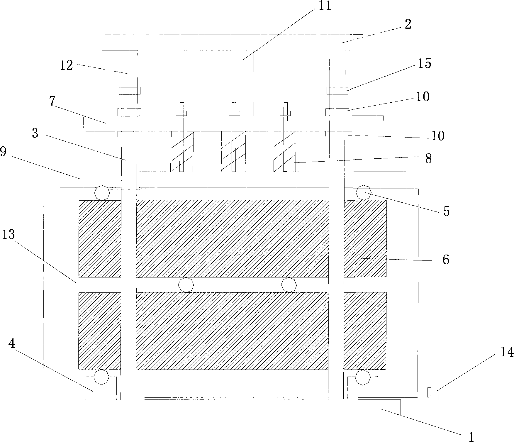
[0016] The device comprises a base plate 1, a pressing plate 7 is arranged directly above the base plate 1, a supporting column 3 is connected between the base plate 1 and the pressing plate 7, one end of the supporting column 3 is fixed on the base plate 1, and the other end is provided with a screw thread and runs through the pressing plate 7; The supporting column 3 is provided with two nuts 10 matched with threads, and the two nuts 10 are located on the upper and lower sides of the pressing plate 7; Two test pieces 6 are clamped between the base plate 1 .

[0017] A jack 11 is provided at the middle part of the upper side of the pressing plate 7 , and the upper side of the jack 11 is in contact with the upper top plate 2 . The lower side of the upper top plate 2 is provided with a connecting rod 12, and the connecting rod 12 and the support column 3 are connected by bolts 15. A water tank 13 is provided between the splint 9 and the bottom plate 1 , and a water outlet valv...

Embodiment 2

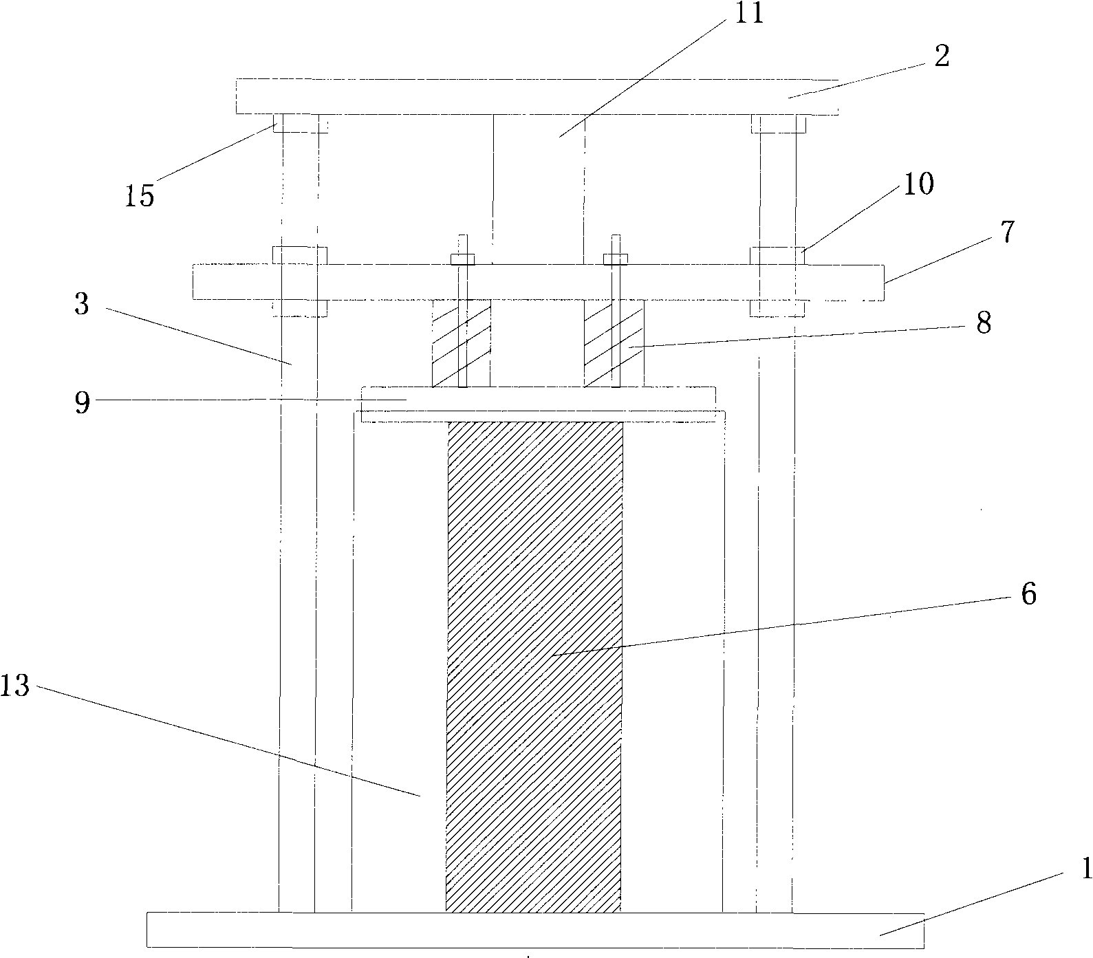
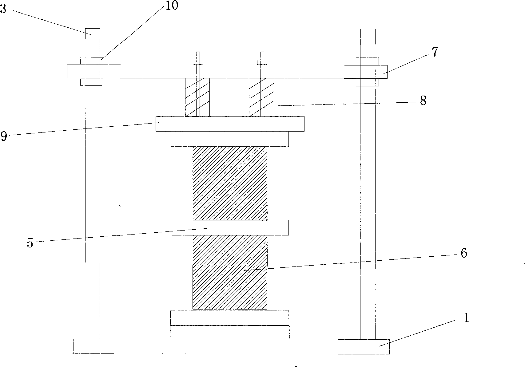
[0020] The device comprises a base plate 1, a pressing plate 7 is arranged directly above the base plate 1, a supporting column 3 is connected between the base plate 1 and the pressing plate 7, one end of the supporting column 3 is fixed on the base plate 1, and the other end is provided with a screw thread and runs through the pressing plate 7; The supporting column 3 is provided with two nuts 10 matched with threads, and the two nuts 10 are located on the upper and lower sides of the pressing plate 7; A test piece 6 is clamped between the bottom plate 1 and the bottom plate 1.

[0021] A jack 11 is provided at the middle part of the upper side of the pressing plate 7 , and the upper side of the jack 11 is in contact with the upper top plate 2 . The upper top plate 2 is connected with the support column 3 by bolts 15 , that is, the upper top plate 2 is directly fixed on the support column 3 by bolts 15 . A water tank 13 is provided between the splint 9 and the bottom plate 1...

Embodiment 3

[0024] The device comprises a base plate 1, a pressing plate 7 is arranged directly above the base plate 1, a supporting column 3 is connected between the base plate 1 and the pressing plate 7, one end of the supporting column 3 is fixed on the base plate 1, and the other end is provided with a screw thread and runs through the pressing plate 7; The supporting column 3 is provided with two nuts 10 matched with threads, and the two nuts 10 are located on the upper and lower sides of the pressing plate 7; Two test pieces 6 are clamped between the base plate 1 .

[0025] The upper side of the bottom plate is provided with a positioning spacer 4 , and the positioning spacer 4 is located directly below the splint 9 . Grooves are arranged on the positioning block 4, and the rollers 5 are embedded in the grooves. Rollers 5 are arranged between the upper and lower test pieces 6 and between the test piece 6 and the splint 9 .

[0026] Put the test piece 6 in the test device, loosen t...


PUM


Abstract

The invention relates to an apparatus using mechanical stress to test solid material strength characteristic, a cement base material dead loading compound corrosion test instrument. The inventive cement base material dead loading compound corrosion test instrument includes a motherboard and a clamp plate equipped above the motherboard, wherein, support upright posts are connected between the motherboard and the clamp plate, one end of the support upright post is fixed on the motherboard, the other end is equipped with screw thread and penetrates the clamp plate; each support upright post is equipped with two nuts copulated to the screw thread, the two nuts are respectively located on the top and bottom sides of the clamp plate; the middle part below the clamp plate is mounted with a spring, the lower end of the spring is fixed with a clamp plate, test pieces are clamped between the clamp plate and the motherboard. The apparatus has simple structure, convenient operations, easy load exerting and control; can maintain the test piece model at a stable load level for a long term, thereby providing dependable experimental device and approach for investigating material durability problem under compound action of load and corrosion surroundings.

Description

technical field [0001] The invention relates to a device for testing the corrosion resistance performance of solid materials in composite environments by using long-term mechanical stress. Background technique [0002] Buildings made of cement-based materials must bear certain loads during their service period. Therefore, in the process of corrosion, cement-based materials must also bear the effect of loads, that is, the materials face damage under the combined factors of load-corrosion ions. Research has shown that material failure caused by one action (both mechanical and environmental) can exacerbate the effects of other factors. In fact, there is a great correlation between the effects of various factors, which makes the influence of compound factors on the corrosion performance of materials more complicated. Therefore, the existence of load will greatly affect the durability of cement-based materials. [0003] At the same time, the corrosion process of cement-based ma...

Claims


Application Information

Patent Timeline
Patent Type & Authority Applications(China)
IPC IPC(8): G01N33/38G01N3/08
Inventor 赵铁军姜福香万小梅苏卿
Owner QINGDAO TECHNOLOGICAL UNIVERSITY
Why Eureka
Try Eureka