Method and node for establishing time slot in wireless mesh network

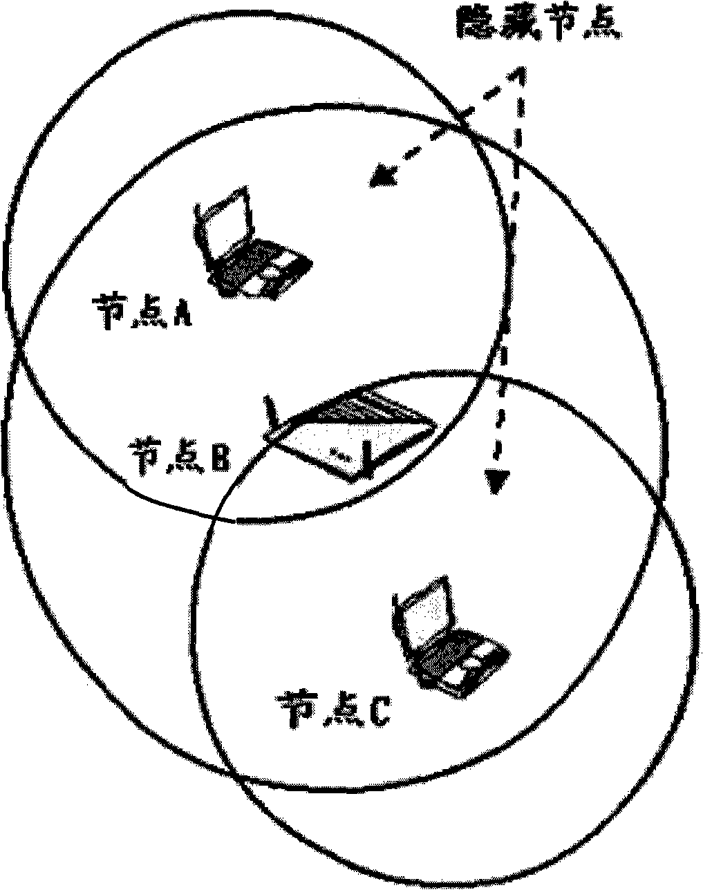
A wireless mesh network and time slot technology, applied in time division multiplexing system, data exchange through path configuration, electrical components, etc., can solve problems such as low channel utilization and broadcast message conflicts, and avoid broadcasting Message collision, the effect of improving channel utilization

Inactive Publication Date: 2008-10-08
HUAWEI TECH CO LTD
View PDF1 Cites 18 Cited by
  • Summary
  • Abstract
  • Description
  • Claims
  • Application Information

AI Technical Summary

Problems solved by technology

[0015] Embodiments of the present invention provide a method and node for establishing a broadcast time slot in a wireless mesh network, so as to solve the problem of broadcast message conflict caused by the hidden node problem in the existing wireless mesh network;
[0016] The embodiment of the present invention also provides a method and node for multiplexing time slots in a wireless mesh network to solve the problem of low channel utilization when time slots are established in an existing wireless mesh network

Method used


Image

  • Method and node for establishing time slot in wireless mesh network
  • Method and node for establishing time slot in wireless mesh network
  • Method and node for establishing time slot in wireless mesh network

Examples


Embodiment 1

[0067] see Figure 4 and Figure 5 , Figure 4 is the topology diagram of the first wireless mesh network in the embodiment of the present invention, Figure 5 It is a schematic diagram of time slots occupied by nodes of the first wireless mesh network in an embodiment of the present invention.

[0068] In this embodiment, the time slot type representation of each occupied time slot is represented by a bit, sharing 1 Byte, and the meaning of the bit is shown in the following table:

[0069] Bit 7

Bit 6

Bit 5

Bit 4-0

broadcast / unicast

send / receive

interference / non-interference

reserve

[0070] The significance of the time slot types of each occupied time slot in this embodiment is shown in the following table:

[0071] Time slot type (Bit7-5)

meaning

000

Unicast Receive Slot

001

Unicast reception interference slot

010

unicast sending slot

011

Unicast Transmit Int...

Embodiment 2

[0096] see Figure 4 , Figure 5 , this embodiment still uses Figure 4 The wireless mesh network topology diagram shown, and Figure 5 The schematic diagram of the time slots occupied by the nodes of the wireless mesh network is shown. In this embodiment, the establishment process of the broadcast time slot is completed by sending a broadcast time slot establishment response message by a one-hop node.

[0097] In this embodiment, the type representation of each occupied time slot is represented by a bit, sharing 1 Byte, and the meaning of the bit is shown in the following table:

[0098] Bit 7

Bit 6

Bit 5

Bit 4-3

Bit 2-0

broadcast / unicast

send / receive

interference / non-interference

state

reserve

[0099] Except for the newly added status bit, the others are the same as in Embodiment 1

[0100] Bit 4-3

meaning

00

established time slot

01

The pending time slot accepted by this node ...

Embodiment 3

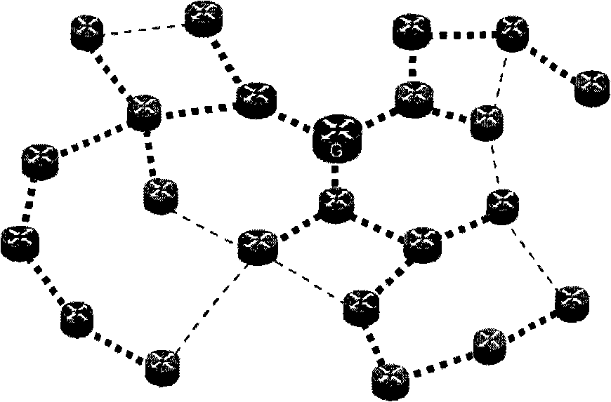
[0116] see Figure 6 , Figure 7 , Figure 6 is the topology diagram of the second wireless mesh network adopted in the embodiment of the present invention, Figure 7 It is a schematic diagram of time slots occupied by the second type of wireless mesh network nodes in the embodiment of the present invention, wherein the meaning of the time slot type of each occupied time slot is the same as that in the first embodiment. This example describes Figure 7 The Node B in the network establishes a broadcast time slot by means of time slot multiplexing, and sends a broadcast message through the established broadcast time slot. The specific implementation process is as follows:

[0117] Step 40: Node B wants to establish a broadcast time slot, and Node B collects the time slot notification messages regularly sent by its neighbor nodes A, C, and E. From the time slot diagram, it can be known that the occupied time slot information announced by A is as follows:

[0118]

[0119] ...


PUM


Abstract

The invention discloses a method for establishing broadcast time slots in a wireless netlike network and a node, the method comprises the steps that: the node collects acquires time slot occupation information of a first-leap and a second-leap nodes by collecting time slot notification message of the first-leap node thereof, the node selects a time slot which is conflict-free with the time slot occupation information to establish the broadcast time slot; the node comprises an time slot occupation information receiving module and a broadcast time slot establishing module, the invention solves the problem about conflict of the broadcast messages resulted by existence of the hidden nodes in current wireless netlike network.

Description

technical field [0001] The invention relates to a WLAN Mesh (wireless mesh network) network, in particular to a method and node for establishing time slots in the wireless mesh network. Background technique [0002] see figure 1 , which is a schematic diagram of the reasons for hidden nodes, where the transmission signal coverage of node A is like the top circle, the transmission signal coverage of node B is the middle circle, and the transmission signal coverage of node C is the bottom circle. When node A uses the carrier sense mechanism to detect that the channel from A to B is idle, node A sends data to node B. Since node C is not within the signal coverage of node A, node C cannot hear the data sent by node A to node B. message, so node C believes that the channel from node C to node B is idle at this time, and node C may also send data to node B at this time, then what node B receives at this time is the superimposed signal of node A and node C, resulting in Node B ca...

Claims


Application Information

Patent Timeline
Patent Type & Authority Applications(China)
IPC IPC(8): H04L12/28H04L5/14H04J3/16
Inventor 杨凯单娜
Owner HUAWEI TECH CO LTD
Why Eureka
Try Eureka