Phased array antenna

A phased array antenna and line technology, applied in antennas, waveguide devices, electrical components, etc., can solve problems such as beam directivity reduction, phase characteristic deviation, beam shape distortion, etc., to maintain directivity gain, less distortion, The effect of high directivity gain

Inactive Publication Date: 2008-10-08
PANASONIC CORP
View PDF4 Cites 48 Cited by
  • Summary
  • Abstract
  • Description
  • Claims
  • Application Information

AI Technical Summary

Problems solved by technology

[0122] Therefore, when the above-mentioned background technology is directly implemented, there are the following problems: deviations occur in the phase characteristics, deviations occur in the variable permittivity characteristics of a plurality of variable phase shifters, and the beam shape is distorted when t

Method used


Image

  • Phased array antenna
  • Phased array antenna
  • Phased array antenna

Examples


Embodiment approach 1

[0366] First, with respect to the phased array antenna of the present invention, an embodiment in which a solid dielectric is used as the variable permittivity dielectric layer will be described.

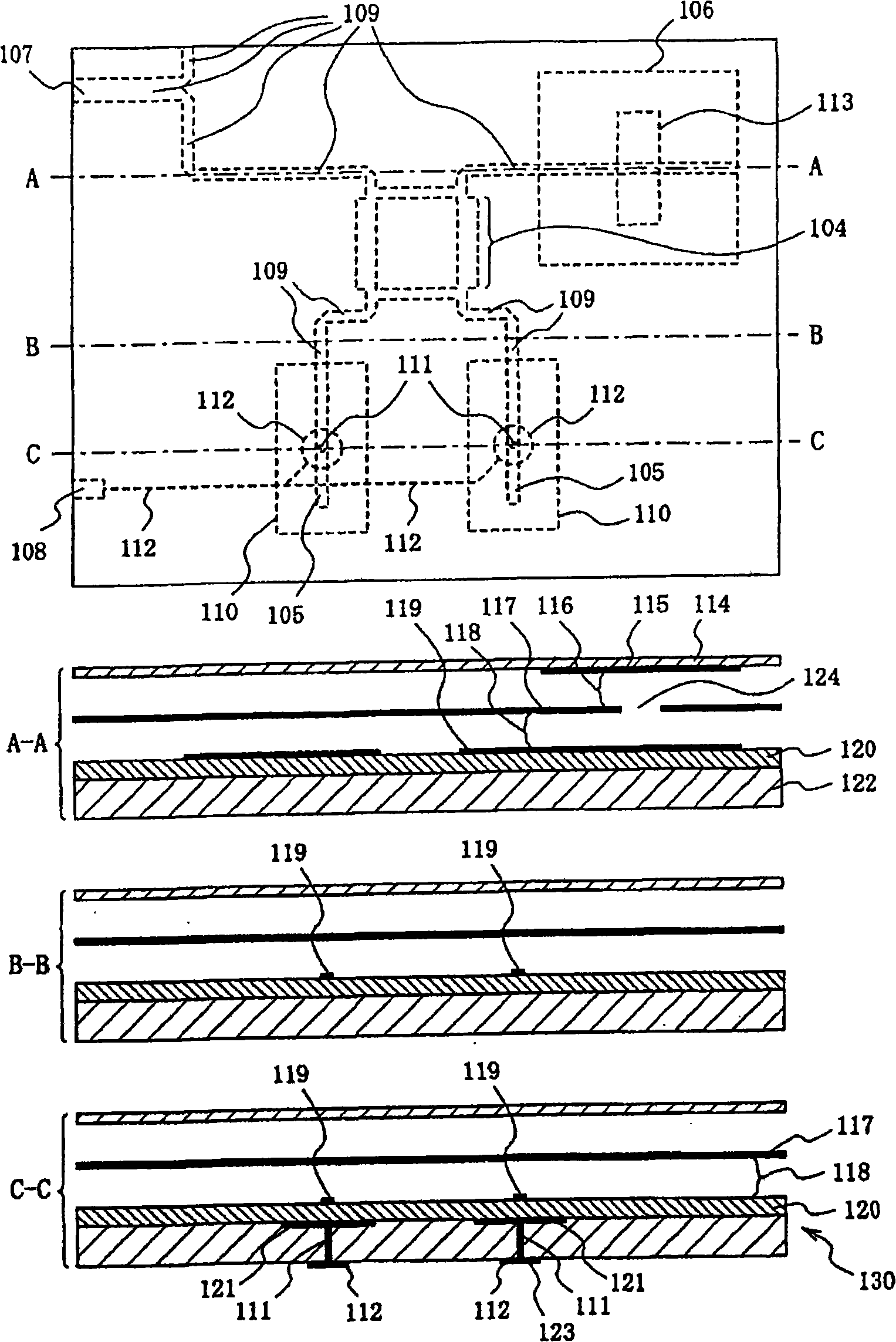
[0367] FIG. 1( a ) is a plan view and a cross-sectional view of a phased array antenna according to Embodiment 1 of the present invention.

[0368] In FIG. 1( a ), the uppermost part in the figure is a plan view showing a state in which the antenna is viewed from the radiation surface side. In the following, A-A line sectional view, B-B line sectional view, and C-C line sectional view sequentially show the state of the section when the antenna is cut at the A-A line, B-B line, and C-C line in the plan view toward the lower side of the figure.

[0369] Here, the display area in the plan view is the same as the display area in FIG. 7 of the antenna of the conventional example.

[0370] In addition, in the plan view, the pattern 104 of the hybrid coupler and the pattern 105 of the var...

Embodiment approach 2

[0396] Next, an embodiment in which a liquid dielectric such as liquid crystal is used as a variable permittivity dielectric layer for the phased array antenna of the present invention will be described.

[0397] Fig. 2(a) is a plan view and a cross-sectional view of a phased array antenna according to Embodiment 2 of the present invention.

[0398] In FIG. 2( a ), the uppermost portion in the figure is a plan view showing a state in which the antenna is viewed from the radiation surface side. In the following, A-A line sectional view, B-B line sectional view, and C-C line sectional view sequentially show the state of the section when the antenna is cut at the A-A line, B-B line, and C-C line in the plan view toward the lower side of the figure.

[0399] Here, the display area of ​​the plan view is the same as the display area of ​​FIG. 7 showing the antenna of the conventional example.

[0400] In addition, in a plan view, the pattern 204 of the hybrid coupler and the patter...

Embodiment approach 3

[0428] Next, an embodiment in which liquid crystal or a material containing liquid crystal is uniformly injected into the phased array antenna of the present invention to form a variable permittivity dielectric layer after constructing the phased array antenna having a laminated structure will be described.

[0429] Figure 10 It is a plan view showing an example of the phased array antenna according to Embodiment 3 of the present invention. exist Figure 10 Among them, the phased array antenna is composed of a stacked structure of a feeding phase shifting unit 308 and an antenna unit 309 .

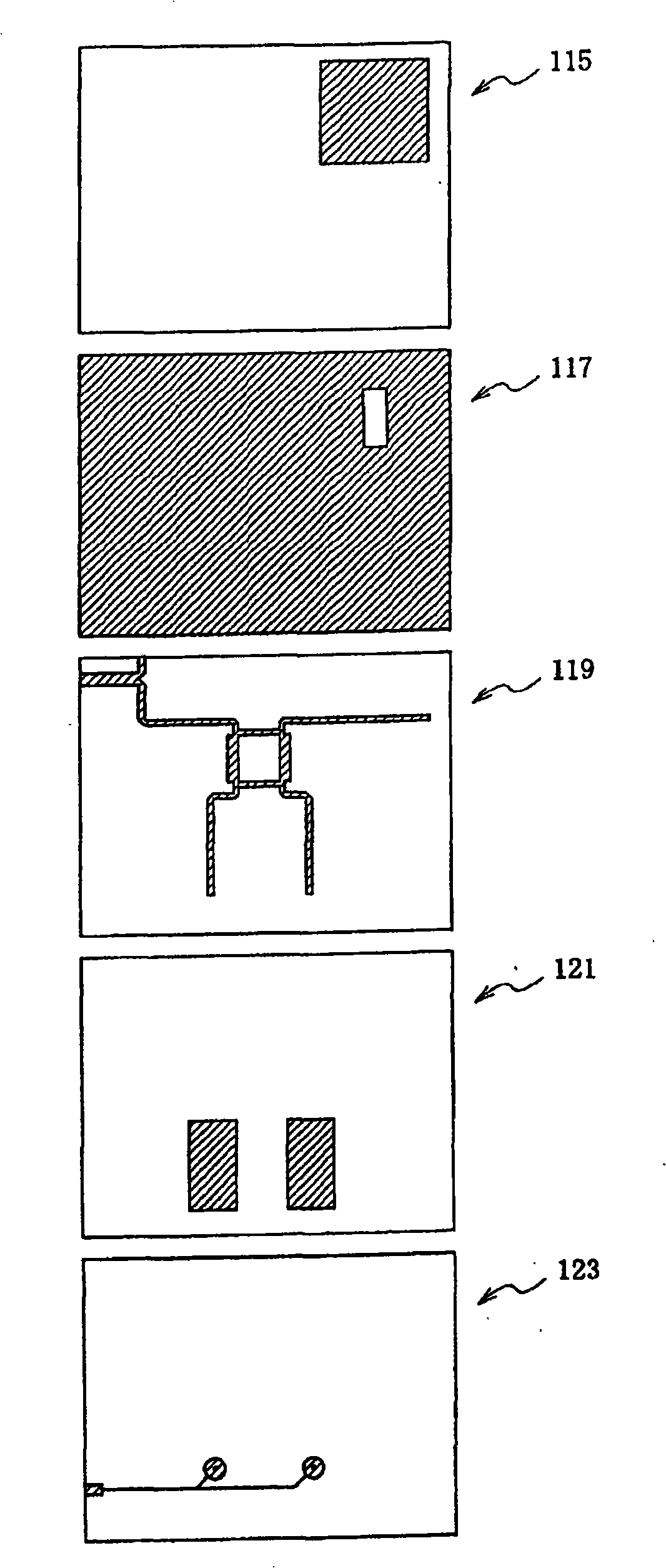
[0430] The power supply phase shifter 308 has: a power supply port 301; a variable phase shifter 302, such as Figure 11 As shown, two propagation characteristic variable lines 115 are arranged substantially parallel to each other; the variable phase shifter 303, such as Figure 12 As shown, two propagation characteristic variable lines 115, a phase shift amount control unit (not shown...


PUM


Abstract

A phased array antenna includes a variable phase shifting device configured by using a variable dielectric constant dielectric body whose dielectric constant is varied by an electric field applied. When the variable phase shifting device is divided into a group of right side tilt and a group of left side tilt, phase amounts of which are controlled independently of each other, it is possible to eliminate a DC inhibit element causing mismatch and realize one having a beam shape which is little deformed during beam tilt. The phased array antenna includes a power supply phase shifting unit (130) having at least a ground conducting layer (117), an insulating layer (118), a main conducting layer (119), a variable dielectric constant dielectric layer (120), and a sub constructing layer (121) which are layered in this order. The power supply phase shifting unit has a propagation characteristic variable line (105) having a line on a region of the sub conducting layer superposed on the line on the main conducting layer. By applying a bias voltage between the main conducting layer and the sub conducting layer, it is possible to change the dielectric constant of the variable dielectric constant dielectric body of the propagation characteristic variable line portion so as to control the propagation characteristic. This eliminates the need of a DC inhibit element inserted in series to the power supply line.

Description

technical field [0001] The invention relates to a phased array antenna. [0002] In more detail, in a phased array antenna having a variable phase shifter constituted using a variable permittivity dielectric whose permittivity changes according to an applied electric field, it is possible to achieve less distortion of the beam shape even when the beam is tilted. , and can maintain high directional gain antenna technology. Background technique [0003] 1) First, Background Art 1 will be described. [0004] Conventionally, as a phased array antenna having a variable phase shifter constructed using a variable permittivity dielectric whose permittivity changes according to an applied electric field, there is an antenna in which the variable phase shifter is divided into right-side tilt By controlling the phase shift amounts of these two groups independently for the left and left tilt, the deviation of the power distributed to each antenna element and the deviation of the phase...

Claims


Application Information

Patent Timeline
IPC IPC(8): H01Q3/34H01P1/18H01P3/08
Inventor 桐野秀树平中弘一畑山健
Owner PANASONIC CORP
Why Eureka
Try Eureka