Reductor slag-removing device
The technology of slag guiding and guiding groove is applied in the field of reducing device slag guiding device, which can solve the problems of bad working environment, heat loss of reducer, high labor intensity, etc. The effect of shortening the time of slag discharge
Inactive Publication Date: 2010-12-01
GUIZHOU SHIJI TIANYUAN MINING IND
View PDF0 Cites 0 Cited by
- Summary
- Abstract
- Description
- Claims
- Application Information
AI Technical Summary
Problems solved by technology
Due to the small diameter of the slag discharge port and the high temperature of the slag discharge port, the temperature of the slag discharge port is very high during slag discharge. The workers work at high temperature, the labor intensity is high, and the working environment is harsh, which greatly affects the slag discharge. High working efficiency, prolonging the time of slagging, causing heat loss in the reducer, and increasing production costs
Due to frequent disassembly and assembly, it will also affect the reliability of the seal of the slag outlet of the reducer
Method used
View moreImage
Smart ImageViewing Examples
Examples
Embodiment Construction
Login to View More PUM
 Abstract
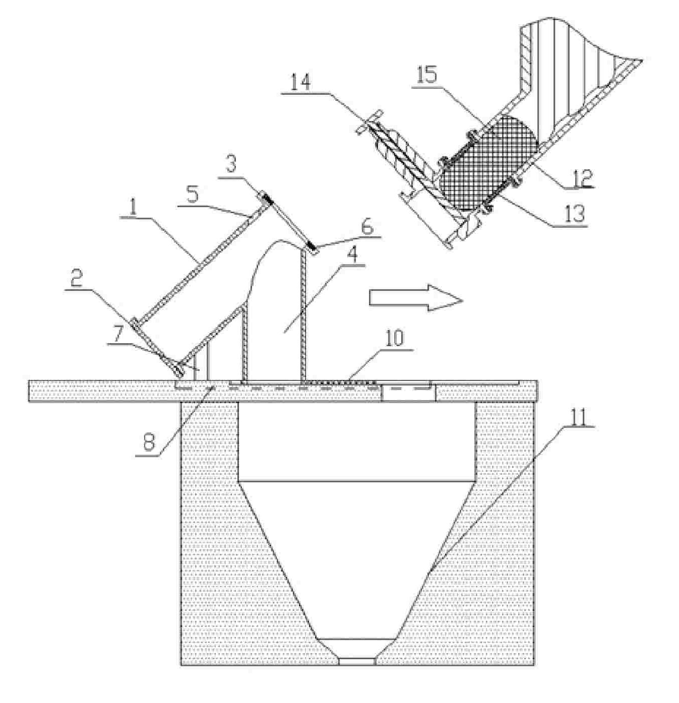
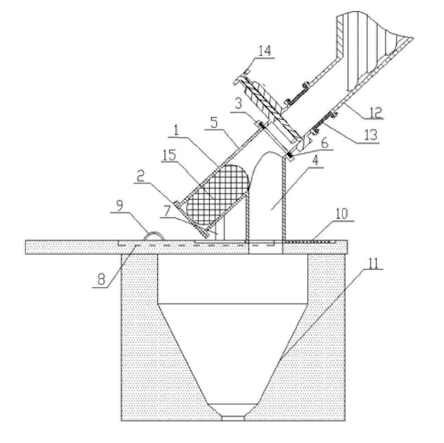
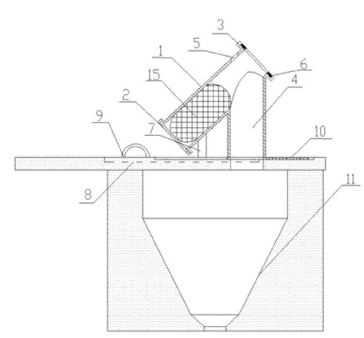
The invention discloses a slag-off device for a reductor (a kettle or a pot). The device comprises an insulator holding section (1) obliquely arranged, an end cover (2) arranged at the bottom of the insulator holding section (1), a movable sealing opening (3) arranged at the top of the insulator holding section (1), and a slag leading pipe (4) connected with the lower part of the insulator holding section (1). Because the slag-off process of the invention is based on sealing condition, the invention can reduce the heat loss in the reductor and also reduce the energy consumption, during discharging off, only a slag-off valve is needed to open, the insulator in the heat insulation section of the reductor automatically slides into the insulator holding section of the invention, reducing slagautomatically flows out from the redactor, and then directly flows into a slag leading groove. The slag-off device for a reductor (a kettle or a pot) improves work efficiency, reduces slag-off time and also reduces heat emission, thus labor environment and labor condition of workers are significantly improved.
Description
Reducer slag guide device technical field The invention relates to a slag guide device, in particular to a slag guide device for a reducer (kettle or tank). Background technique Metal vacuum smelting requires the reduction reaction temperature to be between 1000 and 1300°C, and the internal pressure of the reduction tank to be less than 10Pa to 13Pa. If the reduction reaction is carried out by charging the reducer, a large amount of reduction slag will inevitably be discharged from the reducer after the reduction reaction is completed. In order to improve the sealing degree of the slag discharge port of the reducer and reduce the heat loss in the reducer caused by slagging, the diameter of the slag discharge port should not be too large. Due to the small diameter of the slag discharge port and the high temperature of the slag discharge port, the temperature of the slag discharge port is very high during slag discharge. The workers work at high temperature, the labor inten...
Claims
Login to View More Application Information
Patent Timeline
 Patent Type & Authority Patents(China)
IPC IPC(8): C22B5/02
Inventor 张继强黄贵明
Owner GUIZHOU SHIJI TIANYUAN MINING IND
Features
- R&D
- Intellectual Property
- Life Sciences
- Materials
- Tech Scout
- Unparalleled Data Quality
- Higher Quality Content
- 60% Fewer Hallucinations
Learn More Browse by: Latest US Patents, China's latest patents, Technical Efficacy Thesaurus, Application Domain, Technology Topic, Popular Technical Reports.
© 2025 PatSnap. All rights reserved.Legal|Privacy policy|Modern Slavery Act Transparency Statement|Sitemap|About US| Contact US: help@patsnap.com


