Method and device for friction compensation

A friction compensation and parameter compensation technology, applied in transportation and packaging, strip winding, thin material handling, etc., can solve the problems of huge cost, increase the probability of system failure, unable to optimize the setting adjustment algorithm, etc., and achieve simplification The effect of the algorithm

Inactive Publication Date: 2008-10-22
ROBERT BOSCH GMBH
View PDF1 Cites 10 Cited by
  • Summary
  • Abstract
  • Description
  • Claims
  • Application Information

AI Technical Summary

Problems solved by technology

[0011] All unaccounted-for friction components lead to non-linearization of the regulated object
It will result in the inability to optimize the setting adjustment algorithm, or it will consume a lot of time when setting or trial running the set parameters
thus increasing the probability of failure of the entire system

Method used


Image

  • Method and device for friction compensation

Examples


Embodiment Construction

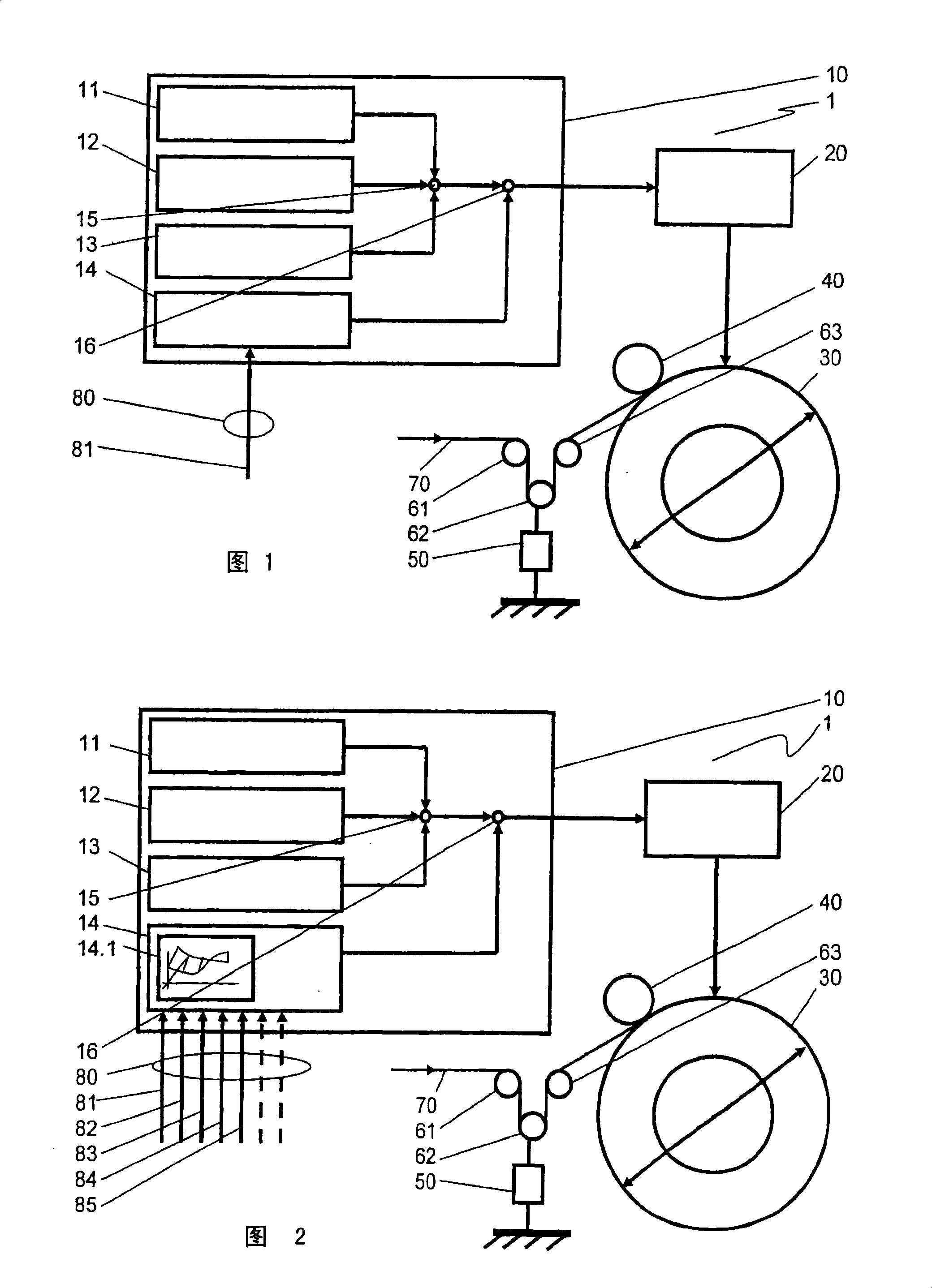
[0036] FIG. 1 shows a winding machine 1 with the essential component winding drum 30 driven by a winding drive 20 . The material 70 to be wound, for example a strip-shaped product, passes first in the illustrated embodiment first through a first deflection device 61, here designed as a fixed roller, and then through a second deflection device 62, here designed as a floating roll The roller is then guided by a third reversing device 63 in the form of another fixed roller, and the material 70 finally leads to the winding drum 30, wherein, in the embodiment shown, the pressure roller 40 compresses the material 70 against the roll. The shaft is wound on the bobbin 30 in order to avoid air entrapment, for example.

[0037] The reversing device 62 is here mechanically connected to the force-measuring device 50 . One side of the force-measuring device 50 is firmly connected to the winder 1 , which force-measuring device can be implemented, for example, as a force cell, by means of w...


PUM


Abstract

The friction compensation device is fitted to a winding machine (1) by which material (70) is wound onto a winding drum (30) controlled by a controlling and regulating device (10). It has an additional process parameter (80) engaged on the input side for compensation of the friction moment in the friction compensation unit (14).

Description

technical field [0001] The invention relates to a method for compensating friction in a winder which winds material onto a winding drum, wherein the winding drum is controlled by a winding drive controlled by a control / regulating device Drive, wherein the drive torque of the winding drive is predetermined in the control / regulating device, wherein the angular velocity of the winding drum is taken into account in the friction compensation unit as an input process variable. [0002] The invention also relates to a device for compensating friction in a winder that can wind material onto a winding drum, wherein the winding drum is controlled by a control / regulation device. drive around the drive, wherein a tension regulator and a diameter calculation unit and / or a friction compensation unit for the linearization of the tension regulator are arranged in the control / regulation device, wherein in the friction compensation unit The angular velocity of the winding drum is taken into ac...

Claims


Application Information

Patent Timeline
Patent Type & Authority Applications(China)
IPC IPC(8): B65H18/08B65H18/26B65H23/195B65H23/198B65H26/04
CPCB65H23/195
Inventor C·米勒H·-J·多雷斯S·舒尔特泽R·克卢斯皮斯
Owner ROBERT BOSCH GMBH
Why Eureka
Try Eureka