
Image forming apparatus

A kind of equipment and imaging technology, which is applied to the equipment, thin material processing, instruments, etc. of the electrical recording process using the charge pattern, and can solve the problems of widening the sealing area, difficulty in ensuring the sealing degree, and poor air intake or exhaust efficiency.

Inactive Publication Date: 2008-10-22
CANON KK
View PDF1 Cites 0 Cited by
  • Summary
  • Abstract
  • Description
  • Claims
  • Application Information

AI Technical Summary

Problems solved by technology

When the distance between the fan and the holding member is further increased, the sealing area becomes wider, making it difficult to ensure the degree of sealing
Therefore, the possibility of intake / exhaust loss increases, and intake or exhaust efficiency becomes poor

Method used


Image

  • Image forming apparatus
  • Image forming apparatus
  • Image forming apparatus

Examples


Embodiment Construction

[0026] Exemplary embodiments embodying the present invention will be described in detail below with reference to the accompanying drawings.

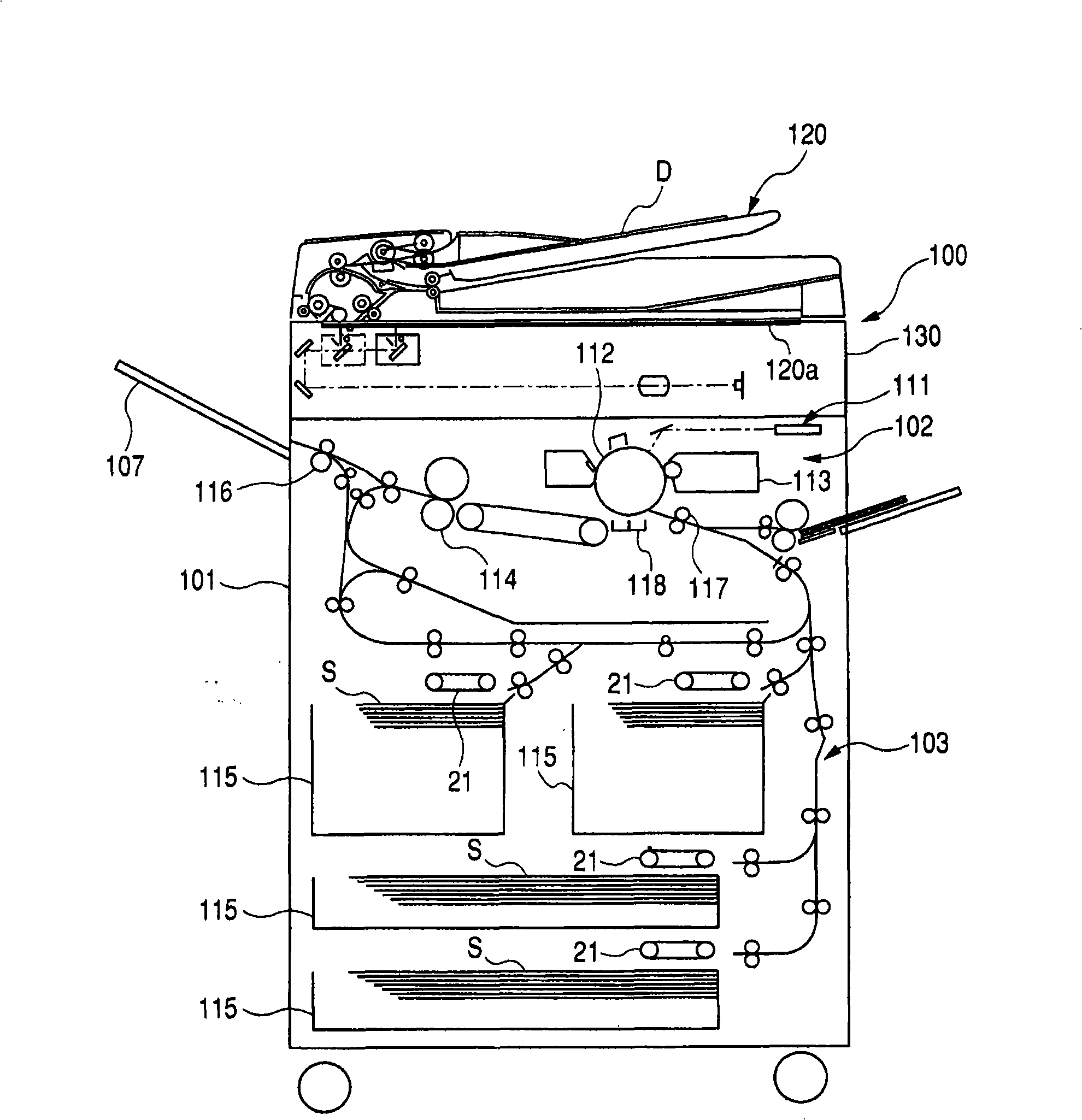
[0027] figure 1 A schematic structure of a printer 100 as an example of an image forming apparatus having a sheet feeding device according to the first embodiment of the present invention is shown.

[0028] exist figure 1 Among them, an image reading section 130 for reading a document D placed on a platen glass 120 a serving as a document setting plate is provided above the printer main body 101 . An automatic document feeder (ADF) 120 for automatically conveying originals onto a platen glass 120 a is arranged above the image reading portion 130 .

[0029] An image forming section 102 and a sheet feeding device 103 for feeding sheets S to the image forming section 102 are provided in the printer main body 101 .

[0030] The image forming section 102 is provided with a photosensitive drum 112 , a developing unit 113 and a laser scann...


PUM


Abstract

An image forming device whose damping component is composed of a clamping part and a main body part, wherein the clamping part is clamped to a surface (8) of a maintaining component located at an opposite side of a maintaining surface of a vibration source and is formed at one end of the main body part; the main body part is inserted into to form in a through hole on the maintaining component, and when the vibration source is fixed by a fixing part, the main body elastically distorts and forms a pressure contact with the vibration source at the same time, and the diameter of the main body part is less than that of the through hole. When the vibration source is fixed, the damping component is clamped to a surface of a maintaining component located at an opposite side of a maintaining surface of a vibration source and is inserted in it with the condition of not forming the contact with the through hole on the maintaining component, and forms the pressure contact with the vibration source (3) so as to enlarge the distance of the propagation path of the vibration.

Description

technical field [0001] The present invention relates to an imaging apparatus, and more particularly, to a vibration damping structure for preventing noise caused by vibration of a vibration generating source. Background technique [0002] Heretofore, image forming apparatuses such as printers, copiers, and the like have sheet feeding devices for feeding sheets one by one from a sheet accommodating portion in which a plurality of sheets are loaded. As for the sheet feeding device, there is an apparatus of an air sheet feeding system in which a plurality of sheets are floated by blowing air to an edge portion of a sheet bundle accommodated in a sheet accommodating portion, only one The sheet is sucked onto the suction conveyor belt arranged at the upper position and conveyed. This technique is disclosed in Japanese Patent Application Laid-Open No. H07-196187. [0003] The sheet feeding device of this air sheet feeding system has: a motor as a driving source of a suction conv...

Claims


Application Information

Patent Timeline
Patent Type & Authority Applications(China)
IPC IPC(8): G03G15/00B65H3/12B65H3/64
CPCF16F15/08G03G15/6532G03G21/00G03G2215/00679
Inventor 板桥俊文池田太郎
Owner CANON KK
Features
  • Generate Ideas
  • Intellectual Property
  • Life Sciences
  • Materials
  • Tech Scout
  • Unparalleled Data Quality
  • Higher Quality Content
  • 60% Fewer Hallucinations
Learn More