
Multicast flow transmission method and system

A technology of multicast streaming and streaming transmission, applied in the field of IP multicast, it can solve the problems of wasting bandwidth, occupying data sending bandwidth, occupying data sending bandwidth of each port, etc., so as to avoid the waste of bandwidth.

Inactive Publication Date: 2008-10-22
NEW H3C TECH CO LTD
View PDF0 Cites 26 Cited by
  • Summary
  • Abstract
  • Description
  • Claims
  • Application Information

AI Technical Summary

Problems solved by technology

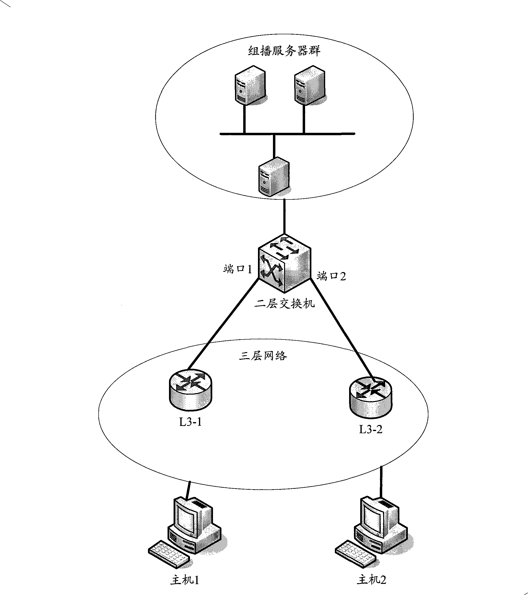
[0007] exist figure 1 , the Layer 2 switch is not directly connected to the multicast receiver, so the multicast stream from any multicast server in the multicast server group is an unknown multicast stream, and the corresponding IGMP-Snooping forwarding entry is empty. , according to the existing solution, the Layer 2 switch will broadcast the multicast flow on all ports except the port receiving the unknown multicast flow, thereby occupying the data transmission bandwidth of each port, and there is a waste of bandwidth
Even if the Layer 2 switch enables the unknown multicast discard function, it will forward the unknown multicast flow to all router ports, but not all Layer 3 devices connected to the router ports need this multicast flow, thus occupying those connections additionally The data transmission bandwidth of the router port of the Layer 3 device that does not need this multicast stream, so there is also a certain waste of bandwidth
[0008] To sum up, in the prior art, when a Layer 2 switch receives an unknown multicast flow, it will always perform broadcast processing or forward the unknown multicast flow to all router ports, while receiving the unknown multicast flow from the Layer 2 switch Not all devices that broadcast streams need this multicast stream, so there is a waste of bandwidth

Method used


Image

  • Multicast flow transmission method and system
  • Multicast flow transmission method and system
  • Multicast flow transmission method and system

Examples


Embodiment Construction

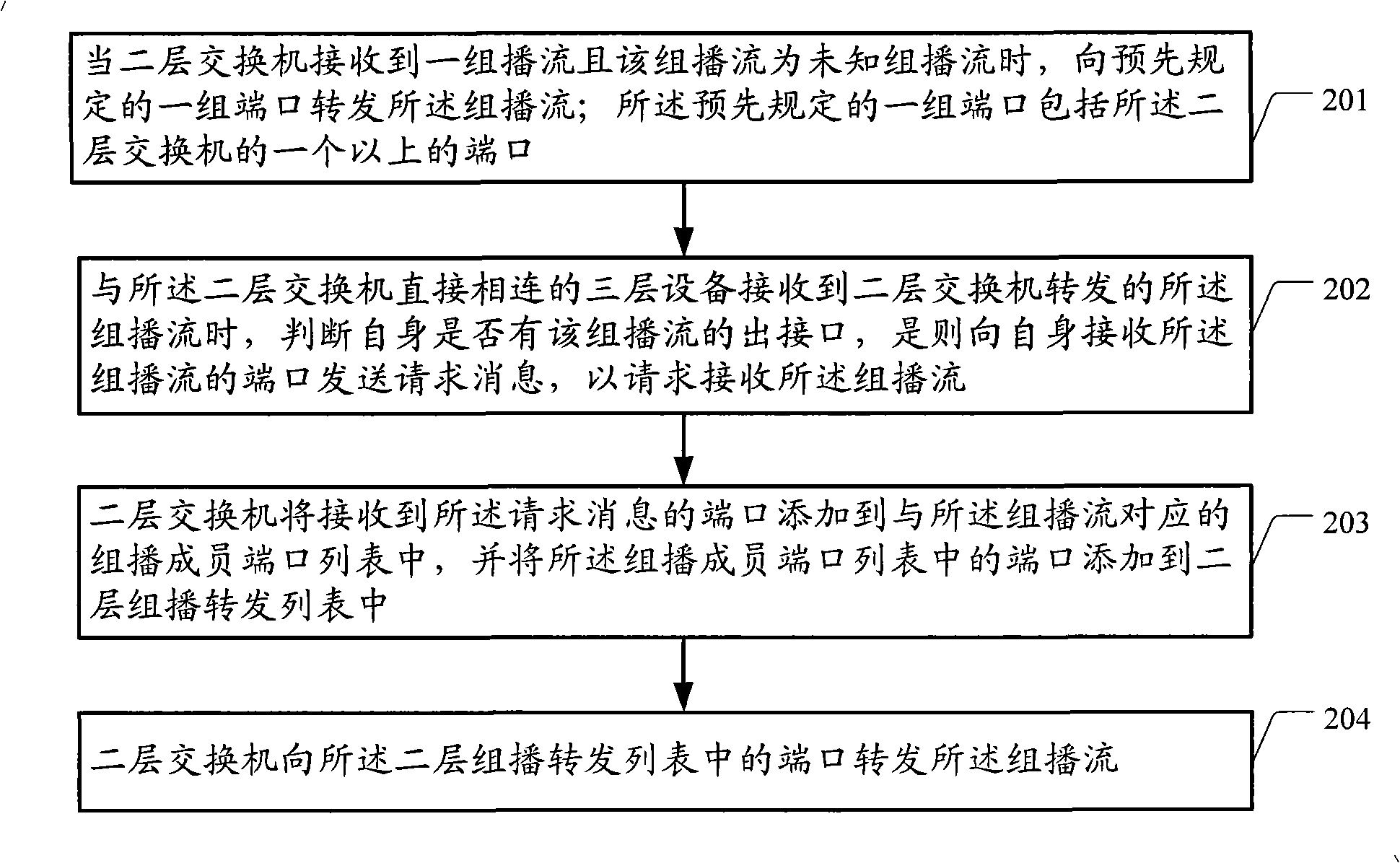
[0034] figure 2 It is a flow chart of a method for transmitting a multicast stream according to an embodiment of the present invention. Such as figure 2 The method shown is applicable to the network in which the multicast flow of the multicast source passes through the Layer 2 switch and the Layer 3 device to reach the multicast receiver in sequence, which includes the following steps:

[0035]Step 201, when a layer 2 switch receives a multicast flow and the multicast flow is an unknown multicast flow, forward the multicast flow to a predetermined group of ports; the predetermined group of ports includes the More than one port of a Layer 2 switch.

[0036] In this step, the predetermined group of ports may be all ports of the Layer 2 switch except the ports receiving the unknown multicast flow, that is, the Layer 2 switch performs broadcast processing on the unknown multicast flow; or the predetermined A group of ports are router ports of the Layer 2 switch; or, the prese...


PUM


Abstract

The invention discloses a multicast stream transfer method, comprising the following steps that: when a double-layer switch receives a group of multicast stream and the group of multicast stream is unknown, the multicast stream is transferred to the preset group of ports; when receiving the multicast stream transferred by the double-layer switch, a three-layer device connected with the double-layer switch judges whether the three-layer device has an outgoing interface of the multicast stream; if yes, a request message is sent to a port of the three-layer device receiving the multicast stream to require to receive the multicast stream; the double-layer switch adds the port receiving the request message to a multicast member port list corresponding to the multicast stream and adds the port in the multicast member interface list to a double-layer multicast transfer list; and the double-layer switch transfers the multicast stream to the port of the double-layer multicast transfer list. The invention also discloses a multicast stream transfer system. The technical proposal of the invention avoids the waste of the bandwidth.

Description

technical field [0001] The invention relates to the technical field of IP multicast, in particular to a multicast flow transmission method and system, a layer-2 switch and a layer-3 device. Background technique [0002] At present, IP multicast technology has been more and more widely used. IP multicast technology refers to: the multicast source (S, Source) sends a multicast IP message, and the destination P address of this message is the address of the multicast group (G, Group), which is a class D address. Only hosts in the multicast group can receive the multicast IP packet. [0003] To realize the forwarding of IP multicast packets in an actual network, that is, the transmission of multicast streams, an interoperable IP multicast routing protocol must be run on each interconnected device. IP multicast routing protocols include: Internet Group Management Protocol (IGMP, Internet Group Management Protocol), Dense Mode Protocol Independent Multicast (PIM-DM), Sparse Mode ...

Claims


Application Information

Patent Timeline
Patent Type & Authority Applications(China)
IPC IPC(8): H04L12/18H04L12/56H04L29/06H04L45/16
Inventor 王杨周迪
Owner NEW H3C TECH CO LTD
Learn More