Thread-connection apparatus

A technology of connecting device and yarn, applied in the directions of transportation and packaging, processing of thin materials, and transportation of filamentous materials, etc., can solve the problems of laborious and complicated replacement of friction discs, and achieve the effect of reliable fixing

Inactive Publication Date: 2008-10-22
SAURER GERMANY GMBH & CO KG
View PDF4 Cites 11 Cited by
  • Summary
  • Abstract
  • Description
  • Claims
  • Application Information

AI Technical Summary

Problems solved by technology

This means that in these known yarn joining devices, changing the friction disc is r

Method used


Image

  • Thread-connection apparatus
  • Thread-connection apparatus
  • Thread-connection apparatus

Examples


Embodiment Construction

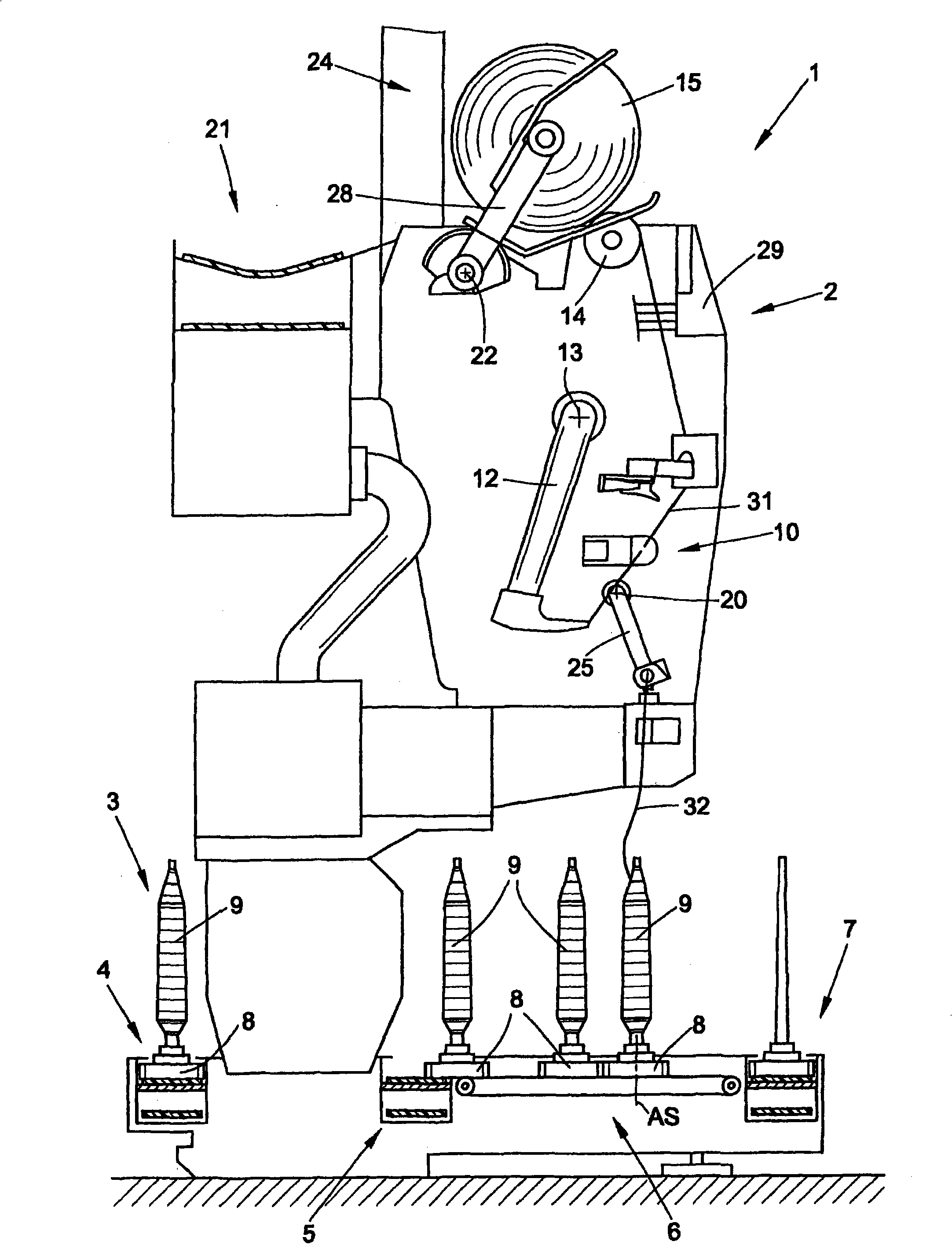
[0026] figure 1 A front view of a textile machine for producing cross-wound bobbins, generally designated by reference numeral 1 , is shown schematically in an embodiment of an automatic cross-winder. Automatic cross-winders 1 of this type generally have between their end frames (not shown) a large number of similar workstations 2 on which textile bobbins 9 already produced by e.g. Rewinding is performed to form bulky cross-wound bobbins 15, these stations are well known and will not be described in detail. After the cross-wound bobbins 15 are produced, they are transferred along the length of the machine to the cross-wound bobbin transfer mechanism 21 by an automatically operating service unit, preferably a cross-wound bobbin changer (not shown), and to the arrangement Package loading station at the end of the machine, etc.

[0027] Automatic cross-winders 1 of this type usually also have a logistics mechanism in the form of a bobbin and bobbin conveying system 3 in which t...


PUM


Abstract

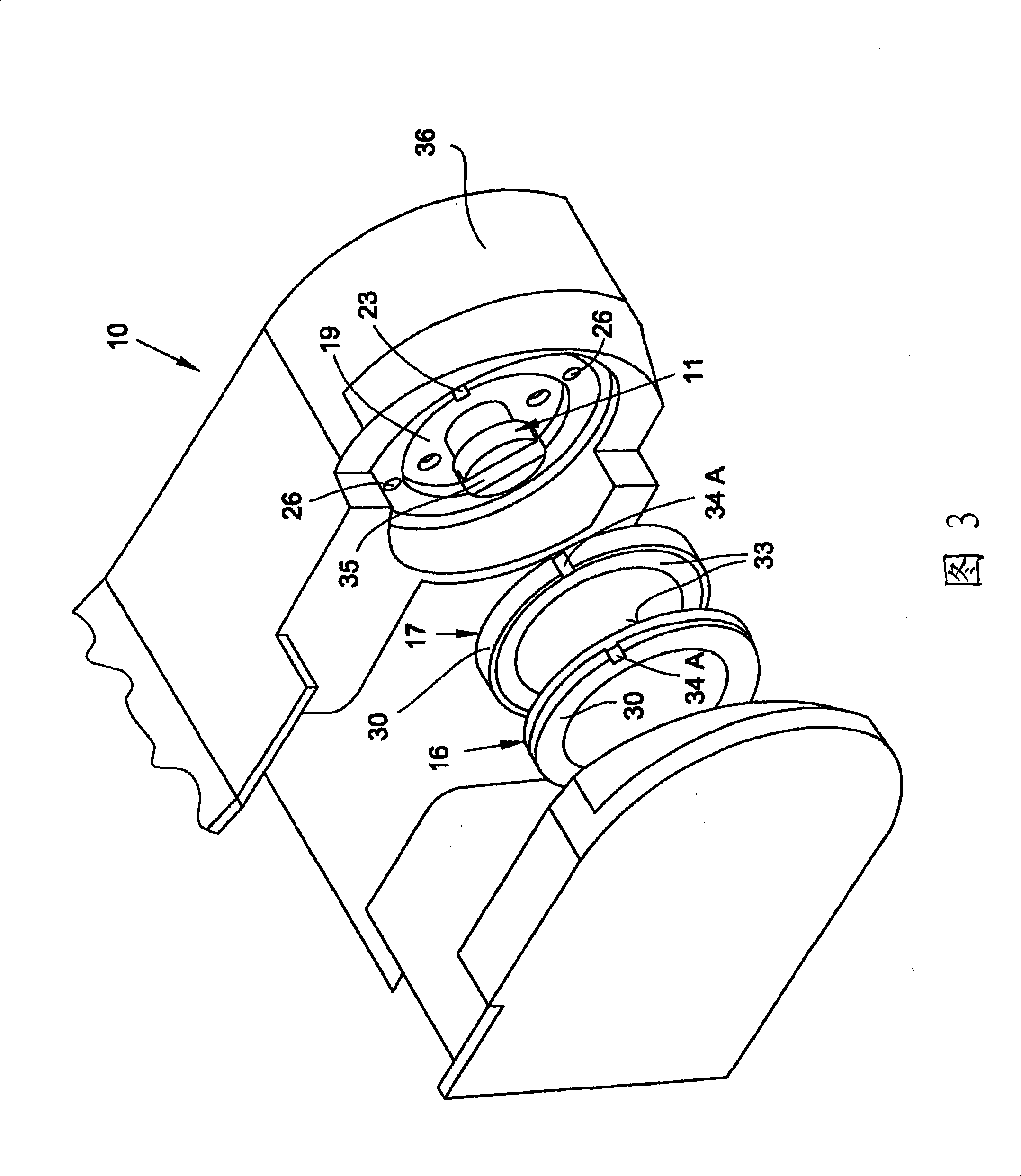
The invention relates to a thread-connection apparatus for connecting two thread ends without using knots, having at least two friction discs which can rotate in relation to one another for the purpose of machining the thread ends to be connected. According to the invention, provision is made for the friction disks (16, 17) to be provided such that they are fixed to holding rings (19) of the thread-connection apparatus (10) by permanent-magnet inserts (26) in a force-fitting manner and are easily accessible, so that it is possible to exchange the friction disks (16, 17) even when the thread-connection device (10) is installed.

Description

technical field [0001] The invention relates to a yarn joining device according to the preamble of claim 1 . Background technique [0002] In particular, yarn joining devices associated with automatic cross-winders, for example for pneumatic splicing of two thread ends, have been known for a long time and are described in detail in various embodiments in numerous patent applications. In this case, it is pointed out in many of these patent applications that it is advantageous to prepare the threads to be joined (in other words, to at least partially untwist the yarn) before the actual splicing process. In this case, the thread preparation for the splicing process takes place either pneumatically by means of a so-called thread opener or mechanically, for example by means of reversing friction discs. [0003] DE 44 20 979 A1 describes a yarn splicing device in which a thread opening tube is arranged spaced apart from a splicing channel arranged in a splicing prism, before the ...

Claims


Application Information

Patent Timeline
IPC IPC(8): B65H69/06
CPCB65H2701/31B65H69/06B65H2601/324B65H69/065
Inventor 沃尔夫冈·伊姆恩诺伯特·科雷斯伯恩哈德·舒密芝
Owner SAURER GERMANY GMBH & CO KG
Why Eureka
Try Eureka