

Non-flash groove, non ingot tail smithing method for large-scale wind power principal axle
A wind power spindle and riser technology, which is applied in the direction of manufacturing tools, forging/pressing/hammer devices, forging/pressing/hammering machinery, etc., can solve the problems of many forging processes, low forging efficiency, and increased forging loss, and achieve shortening Effects of forging time, improving forging efficiency, and reducing forging process
Inactive Publication Date: 2008-10-29
JIANGYIN LEGAO ENERGY EQUIP
View PDF0 Cites 6 Cited by
- Summary
- Abstract
- Description
- Claims
- Application Information
AI Technical Summary
Problems solved by technology
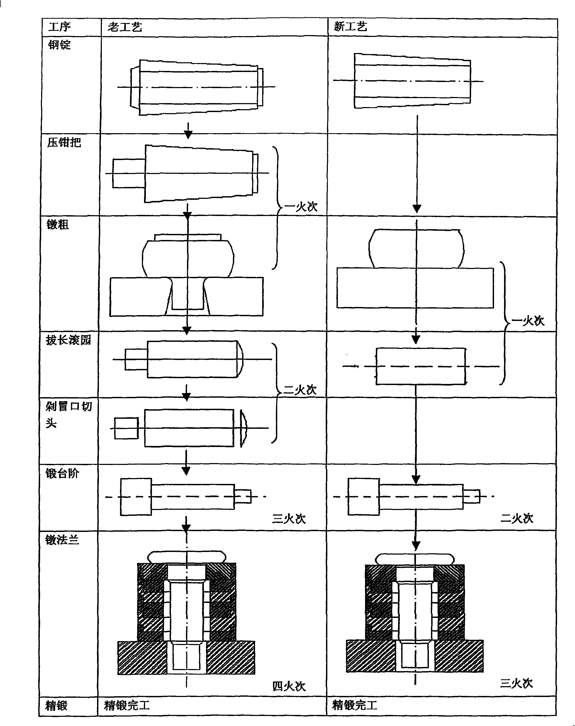
1. In the traditional forging process, the method of pressing the pliers first, then chopping off the pliers and cutting the head after forging is cumbersome and backward
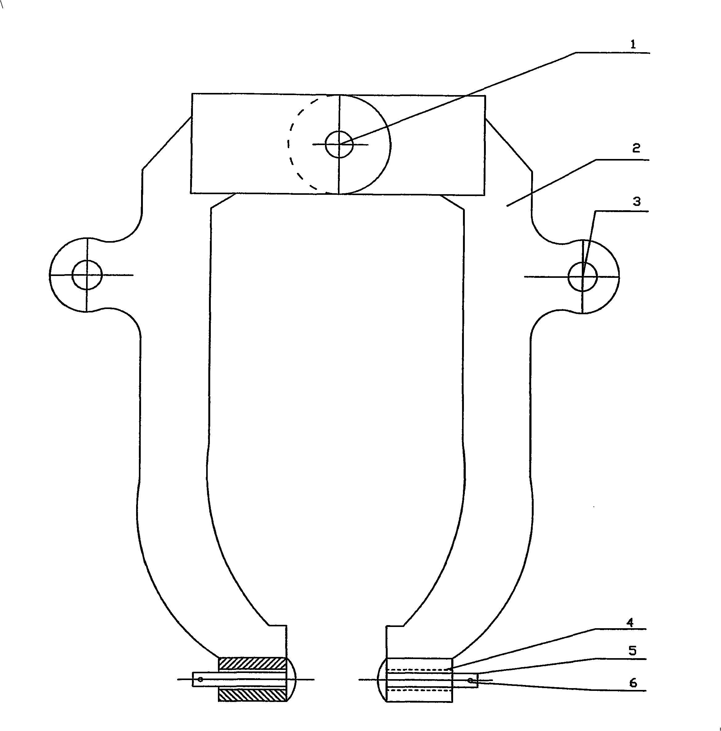
2. The jaws of the traditional manipulator clamps are designed with V-shaped clamps. The opening range of the jaws is small, and it cannot clamp the entire steel ingot from the axial and radial directions of the steel ingot. Therefore, it needs to rely on forging clamps. to achieve
3. There are many forging processes, many heating times, long forging time, low forging efficiency and poor forging precision
At the same time, the heating time of the steel ingot is long, the consumption of natural gas is large, and the production cost is high
4. After the forging is completed, the pliers formed by the riser and the tail of the ingot, the head, and the chopping knife are chopped off, so that the defects of the steel ingot such as shrinkage cavity, deflection, inclusion, and subcutaneous air bubbles cannot be exposed early, which increases the forging process. Unnecessary loss reduces production efficiency
Method used
View moreImage
Smart ImageViewing Examples

Examples
Embodiment Construction
Login to View More PUM
 Abstract
The invention relates to a no-riser and no-ingot tail forging method for a large-scale wind power main shaft; before heating and forging, a riser and a ingot tail of a steel ingot are cut off by a saw, then a jaw of pliers of a manipulator is used for clamping the steel ingot without the riser and the ingot tail, and then the processes of upsetting, drawing out, rolling circle, forging steps and upsetting flange are carried out; the jaw of the pliers of the manipulator includes pliers arms (2), sleeve seats (4) and ball-head cylinders (5); the number of the pliers arms (2), the sleeve seats (4) and the ball-head cylinders (5) is two, one piece is at the left and the other piece is at the right, one end of the left pliers arm (2) is articulated with one end of the right pliers arms (2) by a gemel (1), the other ends thereof are respectively provided with the left sleeve seat (4) and the right sleeve seat (4), the left ball-head cylinder and the right ball-head cylinder (5) are respectively pass through the left sleeve seat (4) and the right sleeve seat (4); the ball-head ends of the left ball-head cylinder and the right ball-head cylinder (5) are arranged at the inner sides of the left sleeve seat (4) and the right sleeve seat (4) in a left and right antithetic manner, and the other ends thereof are provided with a fixed pin (6) by inserting along the radial direction. The method of the invention can reduce forging processes, improve production efficiency, shorten forging time and enhance forging precision and forging quality.
Description
Forging method for large-scale wind power main shaft without riser and spindle tail technical field The invention relates to a forging method for a large-scale wind power main shaft. Mainly used for forging of large wind power main shaft. It can also be used in the production of forgings such as other shafts, parallels, and plates. It belongs to the technical field of forging technology. Background technique When using steel ingots to forge large-scale wind power spindle forgings, the same as forging other shaft forgings, the traditional forging process is that after the steel ingot is heated, the forging always forges the steel ingot riser into a grip that can be clamped by the manipulator clamp, for future Lay the foundation for upsetting, elongating and engraving. After the forging is completed, the pliers formed by the riser and the tail of the ingot, the head, and the head are chopped off with a chopping knife. There are following deficiencies in this forging meth...
Claims
Login to View More Application Information
Patent Timeline
 Patent Type & AuthorityApplications(China)
IPC IPC(8): B21K1/06B21J13/10
Inventor闫盛龙顾晓峰朱国裕杨以振
OwnerJIANGYIN LEGAO ENERGY EQUIP