
Device and method for manufacturing optical elements

A technology for optical components and manufacturing devices, used in manufacturing tools, glass pressing, glass manufacturing equipment, etc., can solve the problems of low material yield and high cold processing cost, and achieve the effect of improving productivity and omitting cleaning

Inactive Publication Date: 2012-08-29
OHARA
View PDF7 Cites 0 Cited by
  • Summary
  • Abstract
  • Description
  • Claims
  • Application Information

AI Technical Summary

Problems solved by technology

However, this method has the disadvantages of high cost of cold working and low material yield

Method used


Image

  • Device and method for manufacturing optical elements
  • Device and method for manufacturing optical elements
  • Device and method for manufacturing optical elements

Examples


Embodiment Construction

[0060] Hereinafter, embodiments of the manufacturing apparatus and manufacturing method of the optical element of the present invention will be described in detail, but the present invention is not limited to the following embodiments at all, and can be implemented with appropriate changes within the scope of the purpose of the present invention. In addition, description may be appropriately omitted for parts that are repeated in description, but this does not limit the gist of the invention.

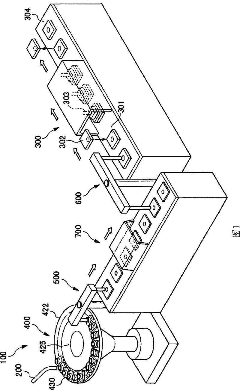
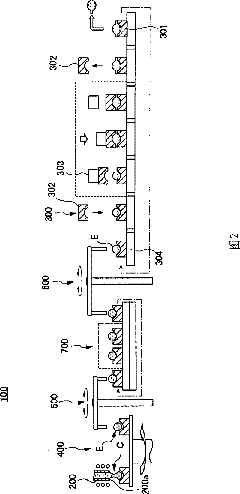
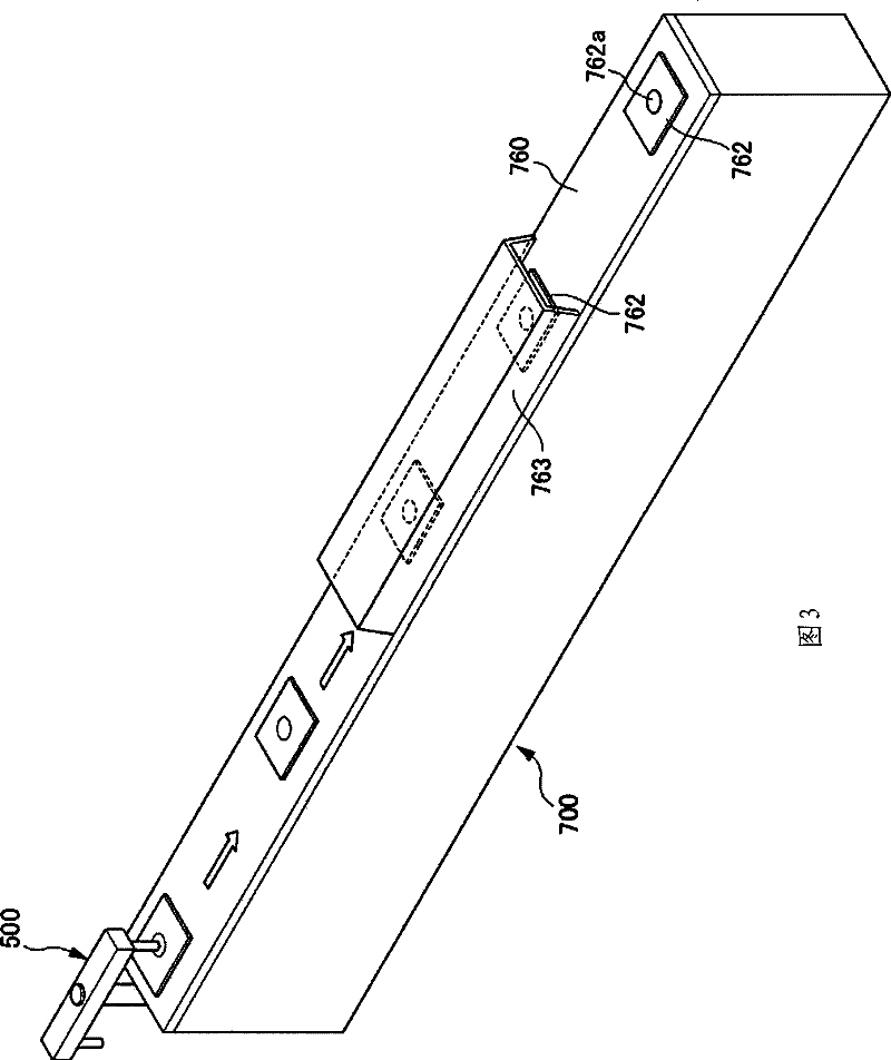
[0061] like figure 1 and figure 2 As shown, a manufacturing apparatus 100 (hereinafter referred to as manufacturing apparatus) for manufacturing optical elements from molten glass includes: a glass block manufacturing apparatus 400 , a precision press molding apparatus 300 , a conveying apparatus 700 , and transfer apparatuses 500 and 600 .

[0062] The glass gob manufacturing apparatus 400 shapes the molten glass C flowing down the channel 200 into a glass gob E using a molding die. ...


PUM


Abstract

The invention provides a manufacturing apparatus which manufactures an optical element by fused glasses for manufacturing preformed body within a time consistent with the time for precise press forming, as well as a method for manufacturing an optical element by fused glasses. The manufacturing apparatus 100 of optical element in the invention comprises: (i) a glass block manufacturing apparatus 400 which fuses optical glasses and cuts the fused glasses into determined volume or mass to form glass blocks; (ii) a conveyor 700 for conveying glass blocks; and (iii) a precise press forming apparatus 300 for precisely press forming the conveyed glass blocks. The manufacturing apparatus 100 of optical element further comprises an adjusting mechanism. The average number of hours which the precise press forming takes in the precise press forming apparatus 300 is set to be a (second / piece); the number of precise press forming apparatus 300 is set to be b; the number of hours which forming of glass block takes in the glass block manufacturing apparatus 400 is set to be c (second / piece); the adjusting mechanism adjusts c to make a / b is not greater than c.

Description

technical field [0001] The present invention relates to a manufacturing device for manufacturing an optical element from molten glass, and a manufacturing method for manufacturing an optical element from molten glass. Background technique [0002] In recent years, miniaturization and thinning are required in the field of optical devices such as digital cameras and projectors, and accordingly, miniaturization of optical elements and reduction in the number of lenses used have become issues. [0003] Generally, the lenses constituting the optical system generally include spherical lenses and aspheric lenses. Most spherical lenses are manufactured by cold working (grinding, grinding, etc.) of glass materials, or by cold working of glass molded articles obtained by reheating press molding. On the other hand, the mainstream processing method of aspherical lenses is to use a mold with a high-precision molding surface to press and form a spherical, ellipsoidal or flat glass block ...

Claims


Application Information

Patent Timeline
Patent Type & Authority Patents(China)
IPC IPC(8): C03B11/08
CPCY02P40/57
Inventor 福田繁树小见川贤辉坂井亮介桑原润一
Owner OHARA
Learn More