
Fan

A technology for fans and centrifugal fans, applied to components of pumping devices for elastic fluids, non-variable-capacity pumps, machines/engines, etc., can solve problems such as increased noise, waste of energy, and shortened fan life.

Active Publication Date: 2008-10-29
DELTA ELECTRONICS INC
View PDF6 Cites 7 Cited by
  • Summary
  • Abstract
  • Description
  • Claims
  • Application Information

AI Technical Summary

Problems solved by technology

However, the disadvantage of this method is that it will simultaneously increase the air flow in areas that do not require such a high heat dissipation effect, resulting in waste of energy, increase in noise, and even shorten the life of the fan

Method used


Image

  • Fan
  • Fan
  • Fan

Examples


Embodiment Construction

[0027] The present invention will be described in detail by taking the following drawings as examples, and the same objects are denoted by the same reference numerals in each of the drawings.

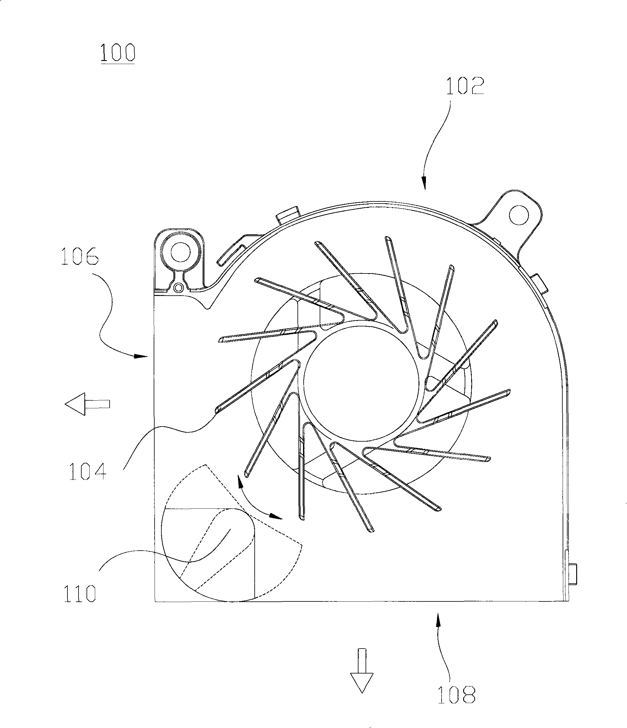
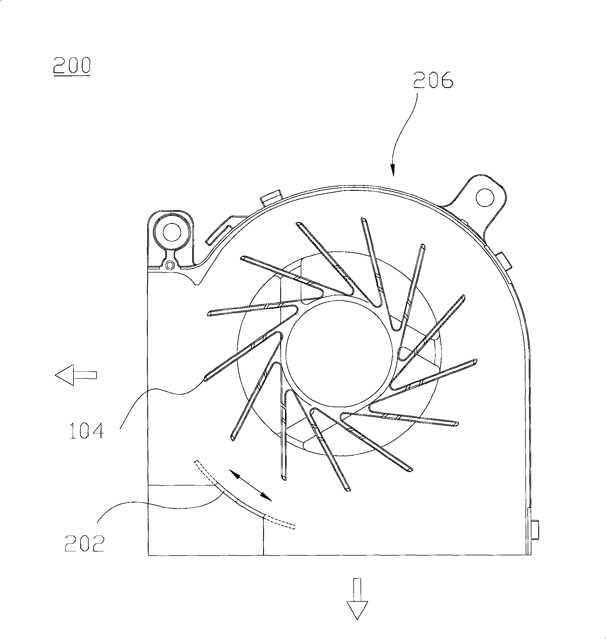
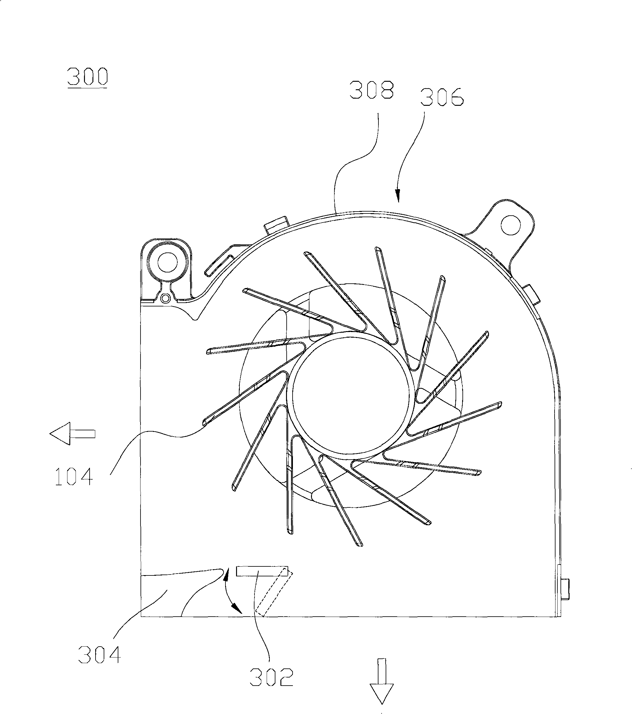
[0028] figure 1 A schematic diagram showing the fan of the first preferred embodiment of the present invention. The fan 100 of the present invention includes at least one fan frame 102 , at least one impeller 104 and at least one active flow regulating device 110 . The fan 100 can be a centrifugal fan. The fan 100 can be connected with a system, and the rotation speed of the impeller can be adjusted according to the control command of the system or the fan 100 itself.

[0029] The fan frame 102 has at least one air inlet and at least one air outlet. In this preferred embodiment, although the fan frame 102 has at least two air outlets 106 and 108 for illustration, it is not limited thereto, and the fan frame 102 may also have at least two air inlets. The fan frame 102 can be integral...


PUM


Abstract

A fan comprises at least a fan frame, at least an impeller and at least an active flow control device; wherein, the fan frame is provided with at least an air outlet and at least an air inlet; the impeller is arranged in the fan frame; the active flow control device is arranged on the fan frame so as to actively change the size of the air outlet or the air inlet according to requirements.

Description

technical field [0001] The present invention relates to a fan, in particular to a fan that actively adjusts the size of an air outlet or an air inlet during operation. Background technique [0002] With the miniaturization and integration of the system, and in order to maintain the electronic components in the system within the normal operating temperature range, a single fan with more than two air outlets is often used to dissipate heat from more than two electronic components at the same time. [0003] However, due to the fact that the heat generated by the various electronic components is not the same, even the various electronic components will have large temperature differences depending on the operating conditions such as idle speed, normal speed, and full speed. Traditionally, when such a situation is encountered, the method of increasing the fan speed is adopted, so that the electronic components with the highest temperature can operate at normal temperature. Howeve...

Claims


Application Information

Patent Timeline
Patent Type & Authority Applications(China)
IPC IPC(8): F04D29/42
Inventor 蔡尚谚林星晨
Owner DELTA ELECTRONICS INC
Learn More