LED lighting lamp

A technology for LED lighting and LED chips, applied in lighting devices, lighting auxiliary devices, lighting and heating equipment, etc., can solve the problem of increasing thermal resistance, limited service life, and not fundamentally solving the problem of heat dissipation of power LED devices, etc. problems, to achieve the effect of improving heat dissipation performance and reliable operation

Inactive Publication Date: 2008-10-29
SHANXI GUANGYU LED LIGHTING
View PDF0 Cites 6 Cited by
  • Summary
  • Abstract
  • Description
  • Claims
  • Application Information

AI Technical Summary

Problems solved by technology

The flip-chip welding method commonly used at present improves the heat resistance of the chip structure, but the cost is very high, and it is difficult to apply LED light sources to general lighting
There are also ways to solve the heat dissipation problem by using a sleeve-shaped tooth structure plus a heat sink and forced convection, but none of them fundamentally solve the heat dissipation problem of power LED devices, which limits the low cost and commercialization of power LED light sources, and Wide application in general lighting
[0006] Secondly, the general LED lighting lamps currently on the market install the constant current source of the lighting lamp inside the radiator. The heat emitted by the light source and the constant current source work together in the heat dissipation body cavity. In the high temperature environment, it directly has a great impact on the constant current source components. When the external ambient temperature is 40°C, the internal temperature of the cooling body cavity can reach 80°C, which greatly reduces the life of the constant current source (for example, although the nominal value of the capacitor The temperature is -40~105°C, but once the actual working environment exceeds 80°C, the capacitor capacity will be reduced by half, and some capacitors with poor quality will even burst
At the same time, under such an ambient temperature, the performance of resistors and transistors becomes extremely unstable, making the lighting unable to work stably)
Therefore, the practice of installing the constant current source in the heat dissipation body cavity makes the service life of the entire product limited by the power supply part, and cannot maximize the long life of the LED.
[0007] In addition, the general LED lighting is to weld the LED light source on the aluminum substrate, and then connect the aluminum substrate to the heat sink. This connection method increases the thermal resistance in the process of heat conduction, and also greatly reduces the heat conduction capacity of the heat sink.

Method used


Image

  • LED lighting lamp
  • LED lighting lamp
  • LED lighting lamp

Examples


Embodiment Construction

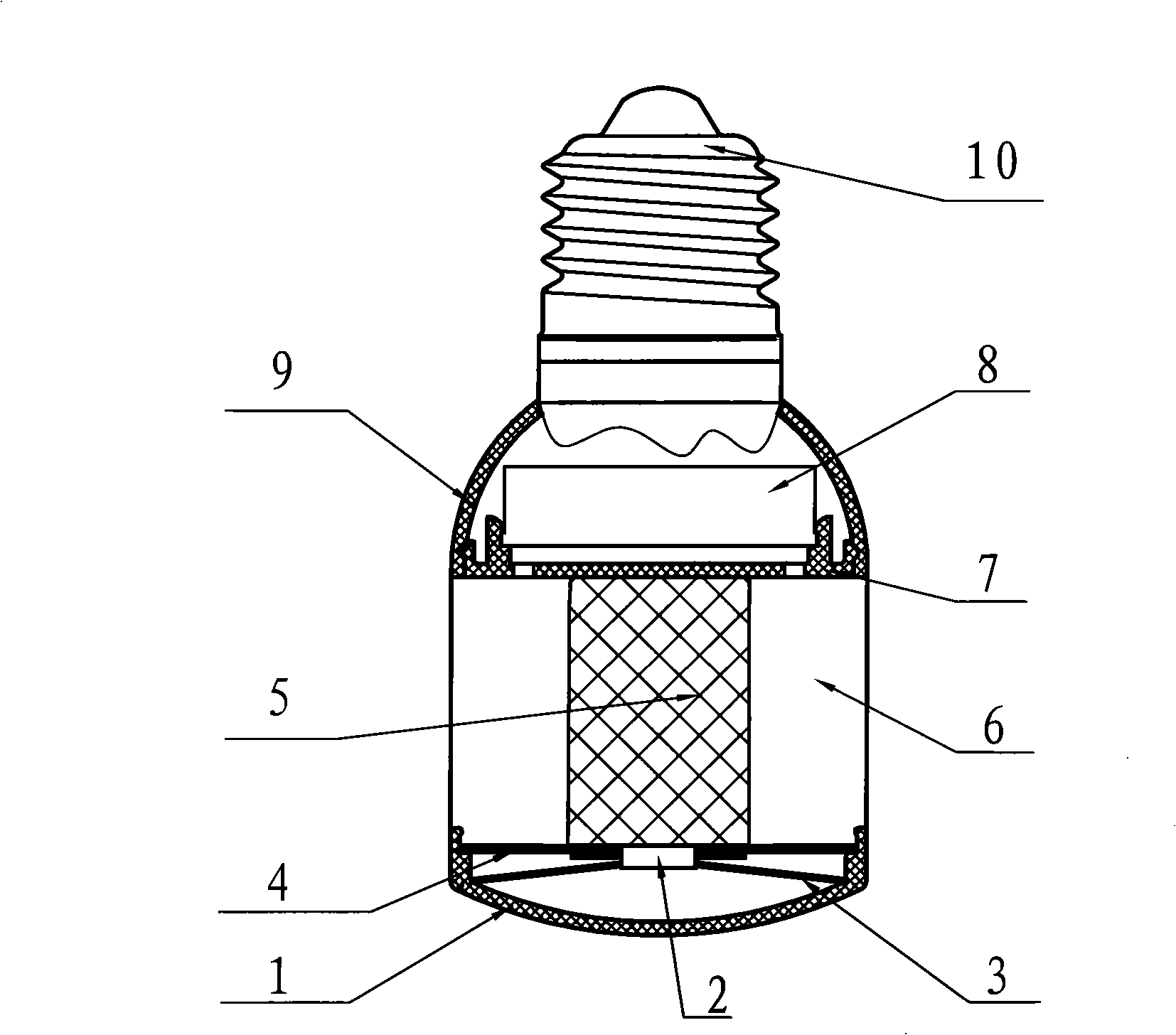
[0035] The LED illuminating lamp of the present invention is as figure 1 As shown, it is mainly composed of three parts: the light source part, the heat sink and the power supply part, among which:

[0036] The heat sink is made of metal aluminum and consists of a solid heat sink base 5 and a plurality of fins 6 radially surrounding the heat sink base 5 for conducting the heat energy generated by the LED lighting to the surrounding air. The fins 6 of the radiator can be made into various shapes that are conducive to increasing the effective heat dissipation area of ​​the radiator, such as Figure 5 The fork-shaped wings shown and the Figure 6 T-shaped wings shown.

[0037] The two end faces of the radiator base 5 are smooth planes, and two through grooves 51 for placing wires are longitudinally arranged on the radiator base 5, and two screw fixing holes 52 are respectively provided on the two end faces, as Figure 5 , Figure 6 shown.

[0038] The light source part is co...


PUM


Abstract

An LED illuminating lamp is composed of a light source part, a radiator and a power supply part. The radiator includes a radiator basal body and wings around the circumference thereof; a light source fixing plate is fixed on an end surface of the radiator basal body, an LED chip is embedded on the light source fixing plate, and a reflector and a lampshade pervious to light are arranged at the front end thereof; a connecting plate is arranged on the other end surface of the radiator basal body, a constant current source is arranged thereon, and the connecting plate is also connected with a lamp housing and a lamp holder. The inventive LED illuminating lamp has outstanding heat dispersion, when the ambient temperature is 25 DEG C, the temperature of the radiator basal body is ranged from 40 DEG C to 50 DEG C, the highest temperature of the constant current source is 55 DEG C, and the LED illuminating lamp can be ensured to work reliably for a long time.

Description

technical field [0001] The invention relates to an LED lighting bulb. The LED bulb of the invention can replace common incandescent bulbs for lighting. Background technique [0002] Because semiconductor lighting has significant advantages such as high efficiency, energy saving, environmental protection, long service life, fast response, vibration resistance, and easy maintenance, it is internationally recognized as a new type of solid-state cold light source that is most likely to enter the field of general lighting. Just as transistors replace electron tubes, semiconductor lamps replace traditional incandescent and fluorescent lamps. [0003] At present, although LEDs have been widely used in indications, LCD backlights, traffic lights, architectural lighting and other fields, there are still many problems to be solved by using LEDs to realize large-scale semiconductor lighting, the most important of which is heat dissipation. [0004] With the increasing maturity of chip...

Claims


Application Information

Patent Timeline
Patent Type & Authority Applications(China)
IPC IPC(8): F21S2/00F21V29/00F21V21/00F21V7/00F21V3/00F21V23/00F21V15/02F21Y101/02F21K9/23F21V29/503F21V29/77F21V29/83F21Y115/10
Inventor 许福贵许敏乔乾亢锐英
Owner SHANXI GUANGYU LED LIGHTING
Why Eureka
Try Eureka