Soft roasting method
A soft-baking and substrate technology, applied in nonlinear optics, instruments, optics, etc., can solve problems such as damage to the display quality and uneven thickness of liquid crystal displays
- Summary
- Abstract
- Description
- Claims
- Application Information
AI Technical Summary
Problems solved by technology
Method used
Image

Examples
Embodiment 1
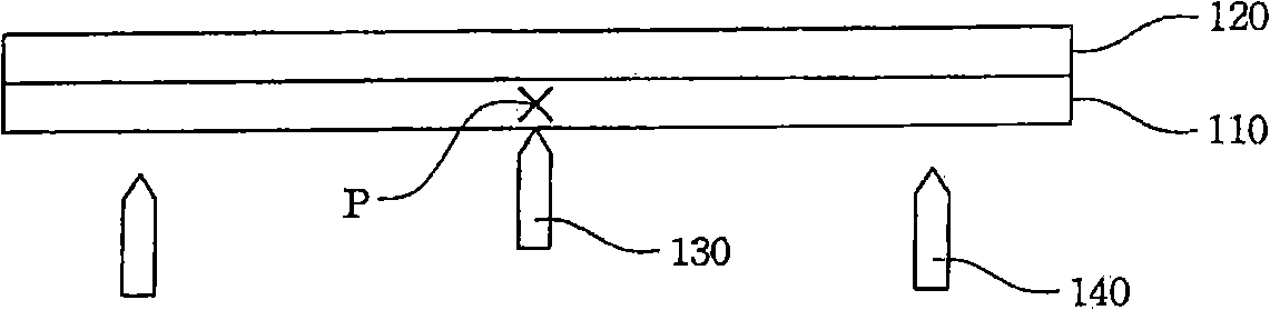
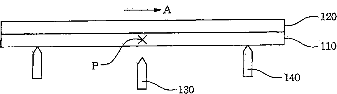
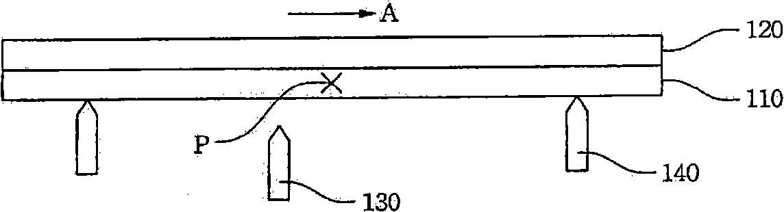
[0024] Figures 1A-1D A schematic diagram illustrating a soft-baking method according to an embodiment of the present invention. As shown in the figure, the user can first coat the alignment liquid 120 on the glass substrate 110, and then place the glass substrate 110 on the thimble 130 of the heating plate, and use the heating plate to heat the glass substrate 110 (such as Figure 1A As shown), the alignment liquid 120 on the glass substrate 110 is dried and solidified to form an alignment film. When heating the glass substrate 110, the user can timely change the position (point P) where the thimble 130 supports the glass substrate 110, so as to prevent the alignment liquid 120 on the point P from drying too quickly, resulting in uneven thickness of the dried alignment film.
[0025] Specifically, the user can use the lifting mechanism 140 to lift the glass substrate 110 away from the thimble 130 while heating the glass substrate 110 (such as Figure 1B as shown). Next, cha...
Embodiment 2
[0028] Figures 2A-2C A schematic diagram illustrating a soft-baking method according to another embodiment of the present invention. Similarly, the user can first coat the alignment liquid 120 on the glass substrate 110, and then place the glass substrate 110 on the thimble 130 of the heating plate, and use the heating plate to heat the glass substrate 110 (such as Figure 2A As shown), the alignment liquid 120 on the glass substrate 110 is dried and solidified to form an alignment film. The difference between this embodiment and Embodiment 1 is: since the cross-sectional shape of the thimble 130 of the present embodiment presents a structure similar to a zigzag (that is to say, the root and the top of the thimble 130 are located on different vertical axes), so use Alternatively, the position where the thimble 130 supports the glass substrate 110 can be changed by rotating the thimble 130 .
[0029] Specifically, the user can use the lifting mechanism 140 to lift the glass ...
Embodiment 3
[0031] Figure 3A-3D A schematic diagram of a soft-baking method according to yet another embodiment of the present invention is shown. The difference between this embodiment and the previous embodiment is that the number of thimbles 130 on the heating plate of this embodiment is multiple, and these thimbles 130 will support the glass substrate 110 in turn (such as Figure 3A-3D As shown), in order to prevent the thimble 130 from contacting the glass substrate 110 for a long time, causing the local temperature on the glass substrate 110 to be too high.
[0032] in particular, Figure 3A-3D The thimbles 130 in the group of four perform simple harmonic motion along the direction perpendicular to the glass substrate 110, wherein the thimbles 130 of the same group have a phase difference of 90° between each other, that is to say, the thimbles 130 are according to The sequence is in contact with the glass substrate 110 . It should be understood that the above-mentioned embodimen...
PUM
 Abstract
Description
Claims
Application Information
 - R&D
- Intellectual Property
- Life Sciences
- Materials
- Tech Scout
- Unparalleled Data Quality
- Higher Quality Content
- 60% Fewer Hallucinations
Browse by: Latest US Patents, China's latest patents, Technical Efficacy Thesaurus, Application Domain, Technology Topic, Popular Technical Reports.
© 2025 PatSnap. All rights reserved.Legal|Privacy policy|Modern Slavery Act Transparency Statement|Sitemap|About US| Contact US: help@patsnap.com