

Electrohydraulic box for high voltage liquid resistor
A liquid resistor, high voltage technology, applied in liquid resistors, motor generators/starters, resistor shells/packaging shells/potting, etc., can solve problems such as temperature rise, increase in production and use costs, and occupation.
Active Publication Date: 2008-10-29
博格华纳新能源(襄阳)有限公司
View PDF0 Cites 3 Cited by
- Summary
- Abstract
- Description
- Claims
- Application Information
AI Technical Summary
Problems solved by technology
Due to the limitation of the design of the electro-hydraulic tank for the existing high-voltage liquid resistance, the existing above-mentioned tank structure presents the following defects: With the long-term operation of the high-voltage AC motor, the two electrodes placed in the electrolyte are continuously released Therefore, it will cause the electrolyte in the box to continuously heat up; therefore, the box containing the electrolyte must be designed to be relatively large, which will undoubtedly increase the volume of the box, and will also increase the production cost and use cost. Occupy a relatively large placement space
Method used
View moreImage
Smart ImageViewing Examples

Examples
Embodiment Construction
Login to View More PUM
 Abstract
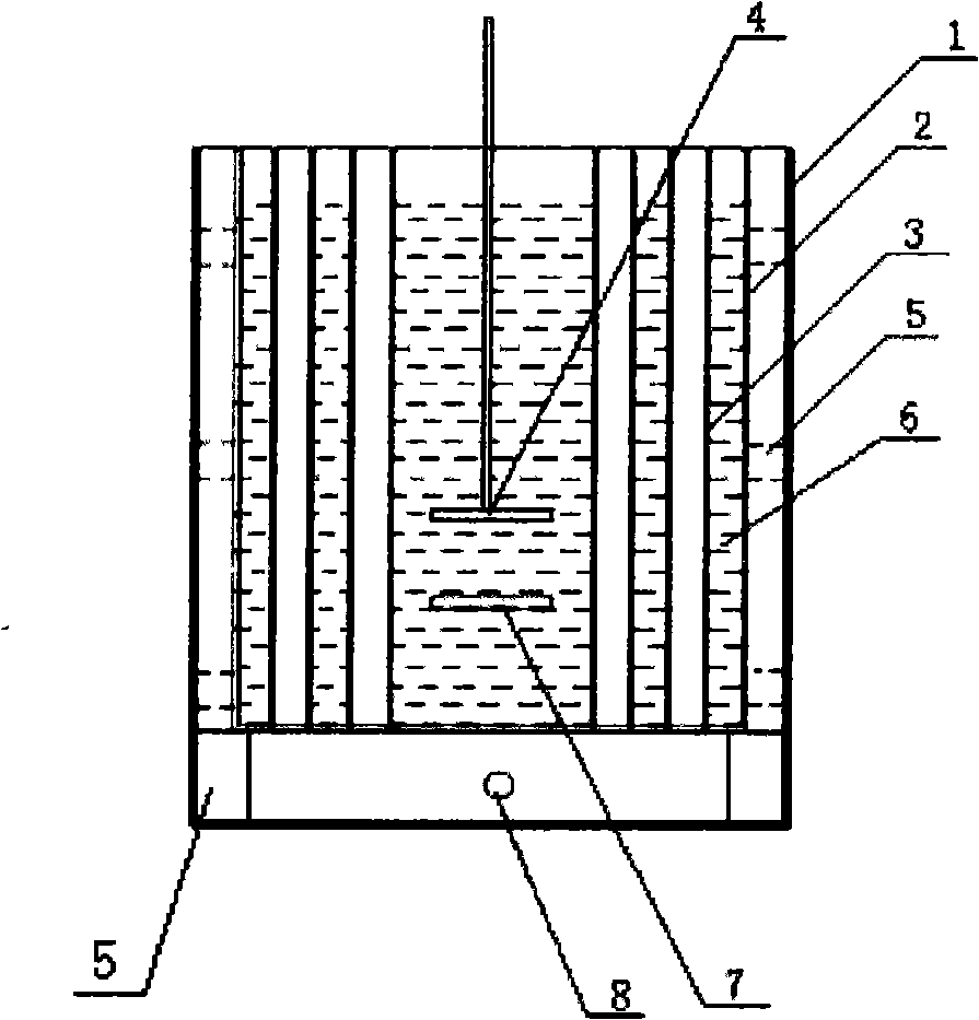
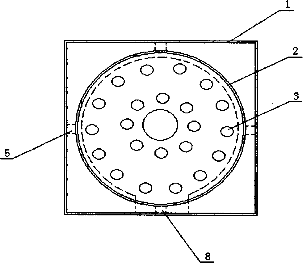
The invention discloses an electrohydraulic box used for a high pressure hydraulic resistance which is composed of a liquid storage box for holding the electrolyte, a fixed polar plate arranged in a box body and a dynamic polar plate; the invention is characterized in that the liquid storage box is internally provided with a plurality of cooling ventilating tubes that penetrate the upper box body and the lower box body; a shell which is preserved with a clearance and provided with an air inlet at the bottom part is sheathed on the periphery of the box body; an isolating supporter is arranged between the box body and the shell; the liquid storage box is made of a glass material; the box body for holding the electrolyte is designed to be a structure mode which is provided with the cooling ventilating tubes, and a shell body is additionally arranged outside the box body, therefore, not only the original use functions of the box body are maintained, but also the size of the box body is reduced, thus being capable of greatly reducing the size of the box body for holding the electrolyte and the use amount of the electrolyte; simultaneously conditions are created for the miniaturization of a soft start device of a whole set of high pressure AC electromotor.
Description
An electrohydraulic tank for high voltage liquid resistance technical field The invention relates to a liquid starting device for a motor, in particular to an electro-hydraulic tank for a high-voltage liquid resistance. Background technique An electrohydraulic tank for high-voltage liquid resistance is an important part of a liquid step-down soft start device for a high-voltage AC motor, and a conductive liquid and moving and fixed electrodes are arranged inside it. The electro-hydraulic tank of the existing high-voltage AC motor liquid step-down soft-start device is actually a common cylindrical or rectangular box welded by metal or non-metallic materials, in which there is a matching device for the soft start of the motor. The movable plate, the fixed plate and the electrolyte for conduction and cooling. Due to the limitation of the design of the electro-hydraulic tank for the existing high-voltage liquid resistance, the existing above-mentioned tank structure presents ...
Claims
Login to View More Application Information
Patent Timeline
 IPC IPC(8): H01C10/02H01C1/02H02P1/02H02P1/36
Inventor陈明
Owner博格华纳新能源(襄阳)有限公司