
High-credibility excitation inrush current braking method of transformer device
A technology of excitation inrush current and transformer, applied in the direction of preventing/reducing unnecessary electric/magnetic influence, electrical components, emergency protection circuit devices, etc., to achieve the effect of improving sensitivity
Patent Information
- Authority / Receiving Office
- CN · China
- Current Assignee / Owner
- Publication Date
- 2008-10-29
- Estimated Expiration
- Not applicable · inactive patent
Smart Images
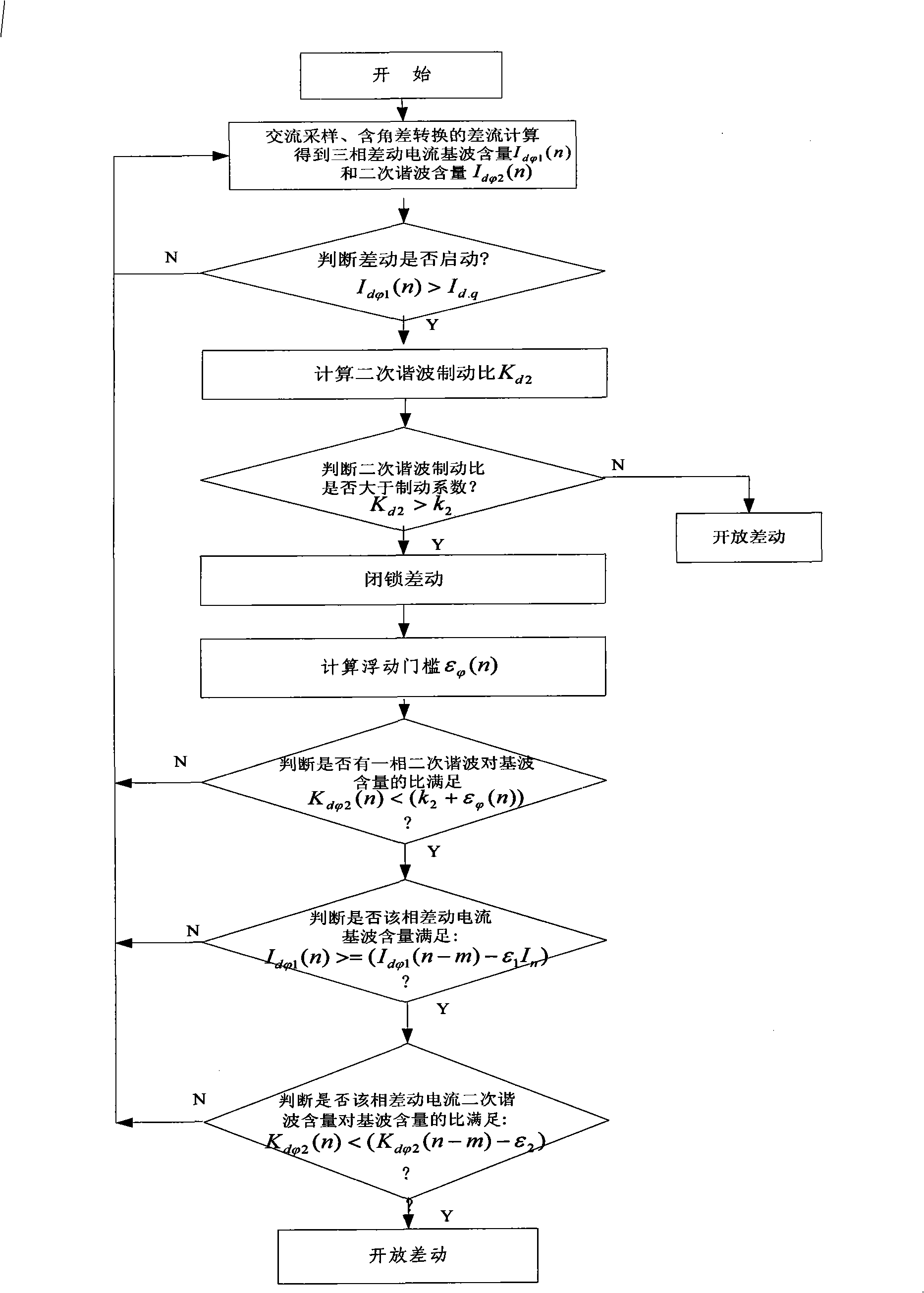
Figure 1 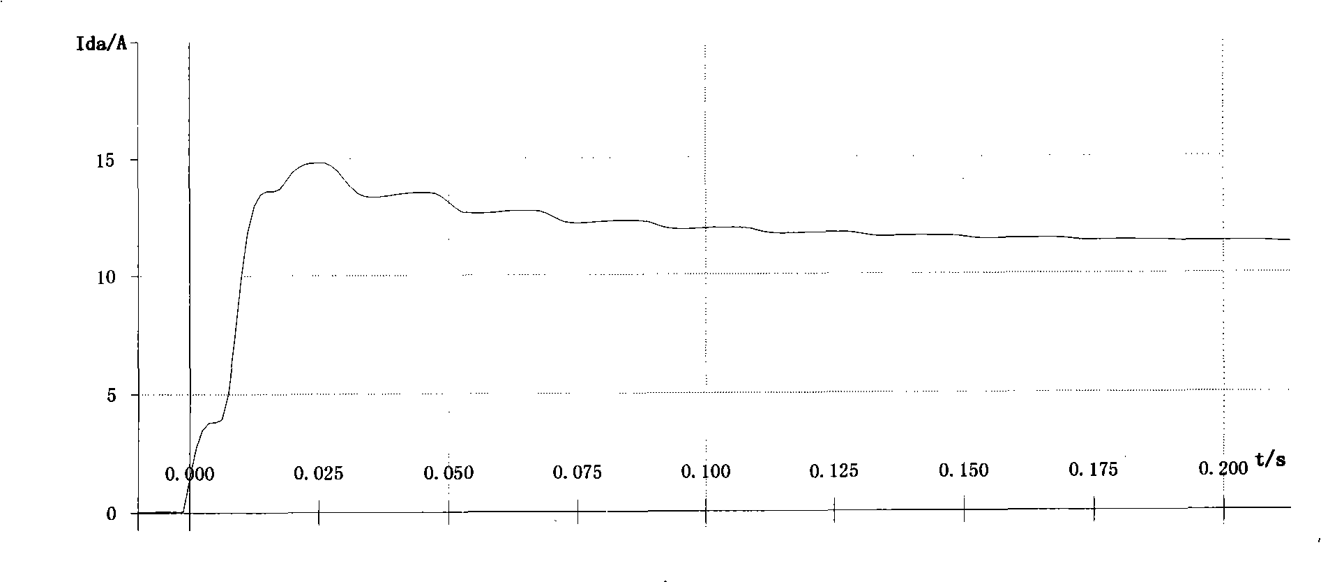
Figure 2 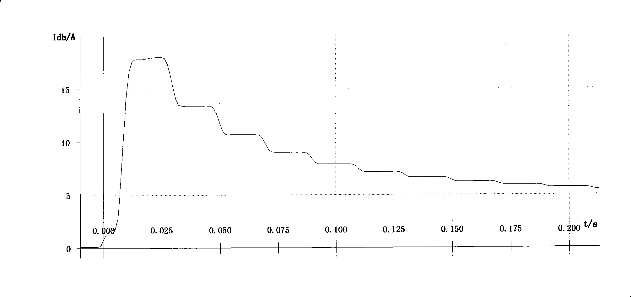
Figure 3
Abstract
Description
technical field
[0001] The invention relates to a differential protection method for a transformer, in particular to a highly reliable excitation inrush current braking method for a transformer. Background technique
[0002] 1.
[0003] Longitudinal differential protection is the main protection of electrical main equipment. It has high sensitivity and good selectivity, and has been successfully applied to main equipment such as generators, reactors, motors, and buses. However, transformer longitudinal differential protection has always been troubled by the problem of excitation inrush current. In the case of no-load closing of the transformer or removal of external faults, an excitation inrush current comparable to the internal short-circuit current will flow into the differential circuit, causing transformer differential protection. Malfunction. Therefore, in some non-internal fault transient processes (such as airdrops and external faults), it is necessary to detect the...
Examples
Embodiment 1
[0035] Example 1: Press figure 1 Steps shown, set the transformer rated current I n =5A; Differential current starting value I d.q =1A (differential current starting value I d.q Given by the user, the general range is 0.1 to 2.0 times the rated current of the transformer); the second harmonic braking coefficient k 2 =10%; the sampling frequency is 1600 points per second, that is, one cycle sampling 32 points, and the value of m is 1 / 2 of one cycle sampling 32 points, that is, m=16, and the reliability coefficient λ=1.0.
[0036] 1. AC sampling, obtain the current sampling value of each side of the transformer, and calculate the differential current including angle difference conversion to obtain the fundamental wave content of the three-phase differential current at the current sampling point n and three-phase differential current second harmonic content And judge the differential start-up: the three-phase differential current RMS waveform diagram when the high volta...
Embodiment 2
[0042] Example 2: Press figure 1 Steps shown, set the transformer rated current I n =5A, differential current starting value I d.q =1A; second harmonic braking coefficient k 2 =10%; the sampling frequency is 2400 points per second, that is, one cycle sampling 48 points, m value is 1 / 2 of one cycle sampling 48 points, i.e. m=24, setting reliability coefficient λ=0.8, setting Fixed threshold coefficient ε 1 and ε 2 The value of ε 1 = 5%, ε 2 = 5%.
[0043] 1. AC sampling, obtain the current sampling value of each side of the transformer, and calculate the differential current including angle difference conversion to obtain the fundamental wave content of the three-phase differential current at the current sampling point n and three-phase differential current second harmonic content And judge the differential start: when the internal ground fault of the A-phase winding on the high-voltage side of the transformer is air-dropped, the three-phase differential current R...