Cut deal high-order steel tapping machines

A tapping machine and high-level technology, applied in furnaces, heat treatment equipment, heat treatment furnaces, etc., can solve the problems of shortening the roller table and buffer device, large impact and noise of the roller table, unmatched heating furnace structure, etc., so as to improve the service life , avoid collisions, and brake reliably

Inactive Publication Date: 2005-02-23
UNIV OF SCI & TECH BEIJING
View PDF0 Cites 11 Cited by
  • Summary
  • Abstract
  • Description
  • Claims
  • Application Information

AI Technical Summary

Problems solved by technology

[0003] The purpose of the present invention is to solve the problem that the lower surface of the slab is easily scratched due to the inclined plane sliding between the heating furnace outlet and the roller table during the process of the slab coming out of the furnace, which affects the surface quality and

Method used


Image

  • Cut deal high-order steel tapping machines
  • Cut deal high-order steel tapping machines

Examples


Embodiment Construction

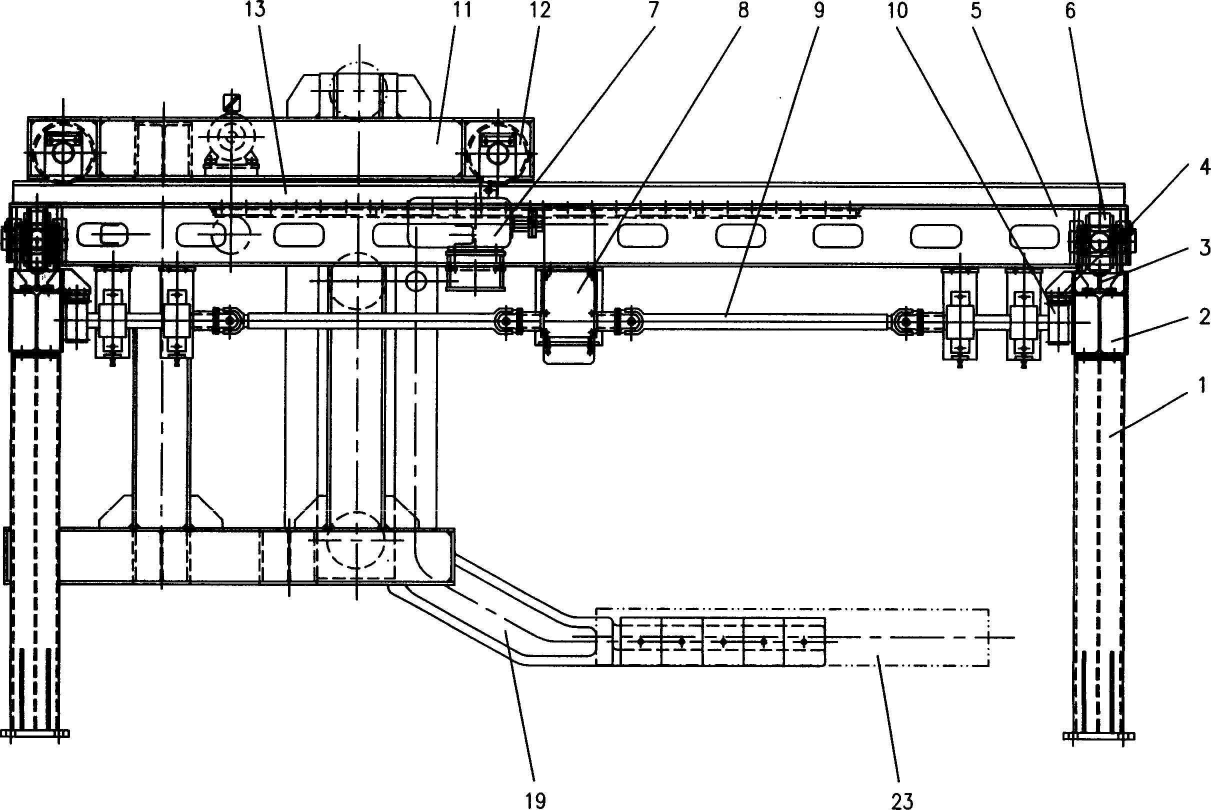
[0014] A high-position steel tapping machine for medium and thick plates, which is composed of a traveling beam, a cart, a trolley, and a lifting mechanism. The traveling beam consists of a column 1, a crossbeam 2, a cart running track 3 and a rack 4 inside the crossbeam (the teeth face downward) constitute. The cart is supported by a glyph-shaped beam body 5, and the glyph-shaped beam body is supported on the cart running track 3 by four passive wheels 6 at four corners. The cart transmission system consists of a motor 7, a reducer 8, and a universal joint shaft 9 , Gear 10 constitutes. When the motor 7 rotates, it drives the reducer 8, the universal joint shaft 9 and the gear 10 to rotate, and the gear 10 meshes with the rack 4 (tooth down) on the inside of the beam to drive the cart to walk.

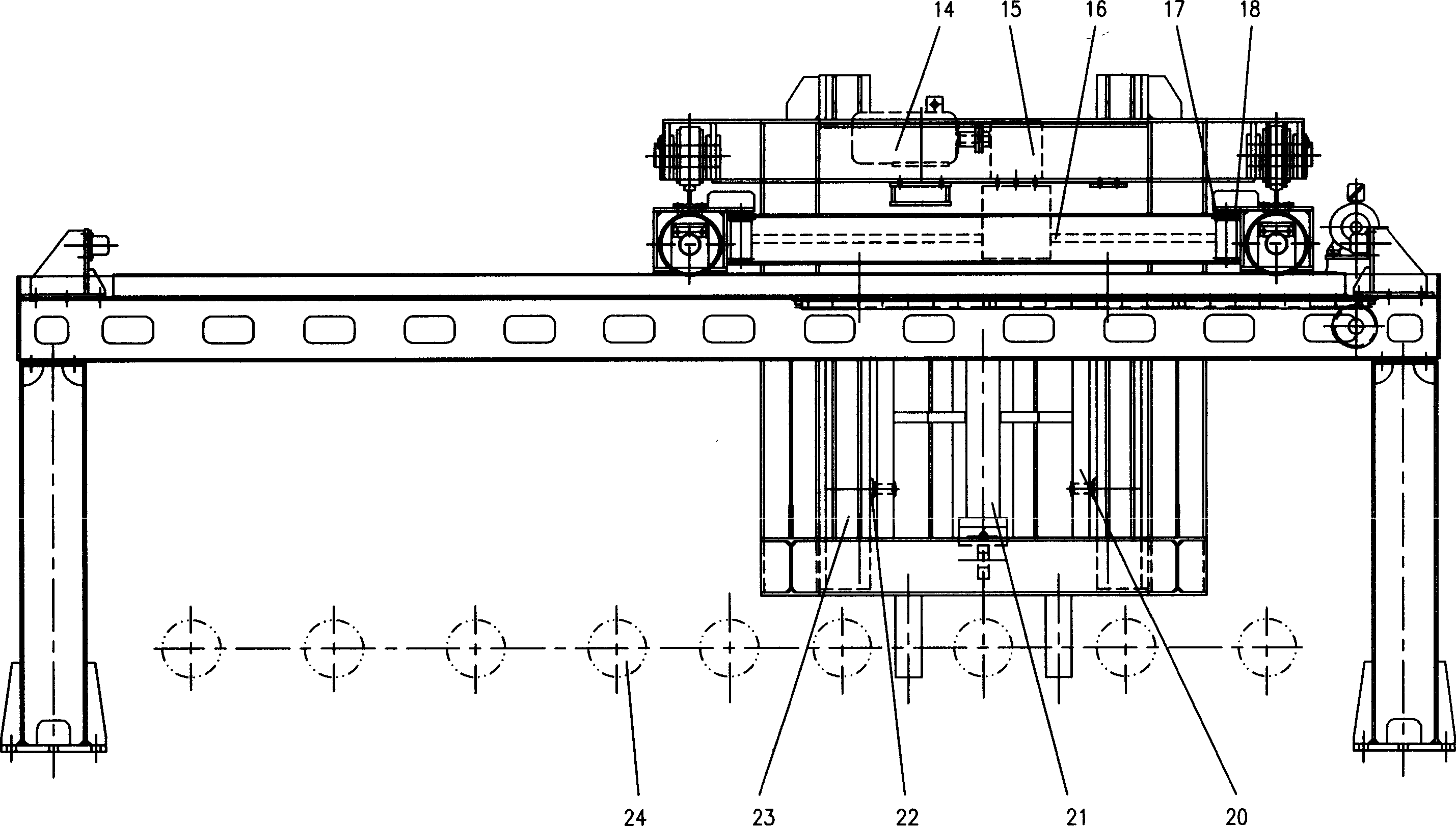
[0015] Dolly is also supported on the cart track 13 by four driven wheels 12 on the four corners by the zigzag beam body 11, the zigzag beam body. The trolley transmission system is...


PUM


Abstract

A plate-straightening high order steel tapping machine consists of walking beam, cart, dan and lifting mechanism. The transversing and longitudinal driving system is used by mechanical transmission and frequency variable control. The lifting mechanism is used by U-shaped groove as guider. The gantry stand is used by self-lubricating wheel. It achieves good safety and long using life.

Description

technical field [0001] The invention belongs to the field of mechanical manufacturing, in particular to a medium-thick plate high-position tapping machine used in front of a heating furnace. Background technique [0002] In the national medium and heavy plate production line, most of the slabs in the heating furnace are released by sliding on the inclined plane between the heating furnace outlet and the roller table, which not only scratches the lower surface of the slab, but also affects the surface quality and quality of the slab. Yield, and a greater impact and noise on the roller table. At the same time, the life of parts such as roller tables and buffer devices is shortened. Before the newly launched or remodeled heating furnace, some factories adopted the structure of the low-position tapping machine (or claiming the slab unloading machine), and the position of the slideway was lowered to be close to the height of the roller table. The basic working principle is as f...

Claims


Application Information

Patent Timeline
IPC IPC(8): C21D9/70
Inventor 阎晓强彭新根
Owner UNIV OF SCI & TECH BEIJING
Why Eureka
Try Eureka