
Transmission method for controlling signaling, network side equipment and terminal

A technology for controlling signaling and transmission methods, applied in transmission systems, digital transmission systems, modulated carrier systems, etc., can solve problems such as inability to linearly precode PMI information, increase system implementation complexity, and not be able to use linear precoding, etc., to achieve Good performance gain and improved reliability

Active Publication Date: 2011-08-10
HUAWEI TECH CO LTD
View PDF0 Cites 0 Cited by
  • Summary
  • Abstract
  • Description
  • Claims
  • Application Information

AI Technical Summary

Problems solved by technology

[0017] Regardless of whether the length of the PMI is fixed or variable, the above prior art will transmit all the PMI information through the data transmission resources. However, this prior art cannot perform linear precoding on the PMI information within the specified RB, and can only use open PMI information is sent in ring diversity mode, therefore, linear precoding cannot be used when transmitting PMI information to obtain better performance gains
[0018] In addition, when only one PMI information is transmitted to the user, for example, in the case of multi-user MIMO, frequency-domain adaptive linear precoding will not be used, and the same linear precoding matrix is ​​used on all allocated resource blocks, and the length of the PMI information In this case, the existing technology also uses a dedicated control channel to transmit PMI information, that is, the PMI information is processed and transmitted separately from other control signaling of the user, which will increase the system implementation. the complexity

Method used


Image

  • Transmission method for controlling signaling, network side equipment and terminal
  • Transmission method for controlling signaling, network side equipment and terminal
  • Transmission method for controlling signaling, network side equipment and terminal

Examples


Embodiment 1

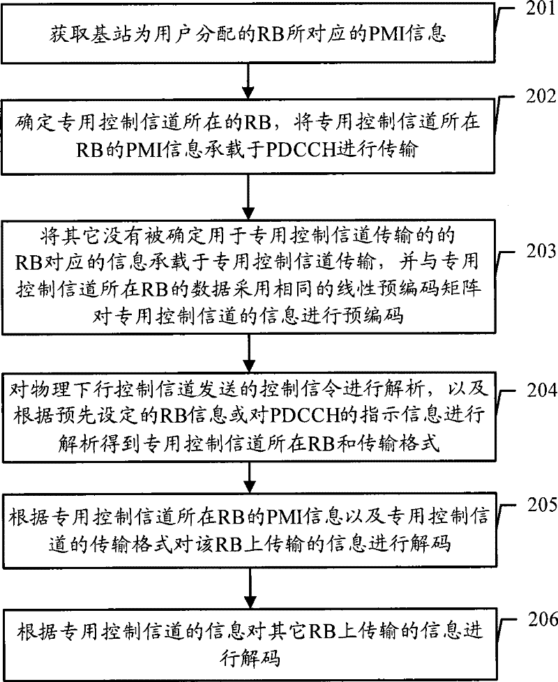
[0047] Embodiment 1. A method for transmitting control signaling. The method flow of this embodiment is as follows: figure 2 As shown, it specifically includes the following steps:

[0048] Step 201: Obtain PMI information corresponding to RBs allocated by a base station to a user.

[0049] Step 202: Determine the RB where the dedicated control channel is located, and carry the PMI information of the RB where the dedicated control channel is located on the PDCCH for transmission.

[0050] Wherein, the RB determined to be the location of the dedicated control channel may be the lowest, highest or any specified frequency position among all RBs allocated to the user.

[0051] If it is a specified location, the information indicating the location is carried on the PDCCH for transmission.

[0052] Step 203: Carry the PMI information corresponding to other RBs not determined to be used for dedicated control channel transmission on the dedicated control channel for transmission, a...

Embodiment 2

[0080] Embodiment 2. A network side device, comprising Figure 8 It can be seen that the device includes an acquiring unit 801 , a bearer unit 802 and a precoding unit 803 .

[0081] Wherein, the acquiring unit 801 is configured to acquire the serial number of the linear precoding matrix corresponding to the resource block allocated by the base station to the user.

[0082] Among them, the carrying unit 802 is used to determine the resource block used for the transmission of the dedicated control channel, and carry the precoding matrix sequence number information of the resource block where the dedicated control channel is located on the physical downlink control channel, and will not be determined for the transmission of the dedicated control channel The corresponding precoding matrix sequence number information is carried on the dedicated control channel.

[0083] Wherein, the precoding unit 803 is configured to use the same precoding matrix as the data of the resource bloc...

Embodiment 3

[0084] Embodiment 3, a kind of terminal, by Figure 9 It can be seen that the terminal includes a receiving unit 901 , an analyzing unit 902 and a decoding unit 903 .

[0085] Wherein, the receiving unit 901 is configured to receive the control signaling carrying the sequence number of the precoding matrix from the physical downlink control channel, and receive the control signaling carrying the sequence number of the precoding matrix from the dedicated control channel.

[0086] Wherein, the analysis unit 902 is used to analyze the control signaling sent by the physical downlink control channel to obtain the resource block allocated by the base station for the user and the precoding matrix sequence number of the resource block where the dedicated control channel is located, and then according to the preset resource block information or The indication information in the physical downlink control channel is analyzed to obtain the resource block where the dedicated control channe...


PUM


Abstract

The invention relates to the technical filed of wireless communication, which discloses a transmission method, network side equipment and a terminal for signaling control, wherein, the method comprises the steps that: a linear pre-coding matrix sequence number corresponding to a resource block allocated to users by a base station is obtained; the resource block used for the transmission of a special control channel is determined, and the information of the pre-coding matrix sequence number of the resource block in which the special control channel is positioned is loaded to a physical downlink control channel; a linear pre-coding matrix which has the same data with the resource block in which the special control channel is positioned is adopted to carry out pre-coding processing to the information loaded by the special control channel. The method, the network equipment and the terminal of the invention cause PMI information corresponding to most RB to obtain performance gain by the pre-coding processing during transmission, thereby promoting the reliability of PMI information transmission.

Description

technical field [0001] The present invention relates to the technical field of wireless communication, and in particular to a control signaling transmission method, network side equipment and a terminal. Background technique [0002] In the E-UTRA (Evolved Universal Terrestrial Radio Access) system of the third generation cooperation project, linear precoding can be used in the downlink using a closed-loop multiple input multiple output (MIMO, Multiple Input Multiple Output) transmission mode Down. The downlink of the E-UTRA system adopts Orthogonal Frequency Division Multiplexing (OFDM, Orthogonal Frequency Division Multiplexing) as the basic modulation technology, and the processing process of linear precoding at the transmitting end of the system is as follows: figure 1 shown. [0003] Modulate the encoded data packet, and map the modulated signal to n layers (Layer) according to certain rules, and the number n of layers is equal to the number of column vectors in the p...

Claims


Application Information

Patent Timeline
Patent Type & Authority Patents(China)
IPC IPC(8): H04L27/00H04B7/26H04B7/04
Inventor 马蒂斯·温斯特姆李洋
Owner HUAWEI TECH CO LTD
Learn More