Tapered roller bearing

A technology for tapered roller bearings and raceways, which is applied in the field of tapered roller bearings, can solve the problems of not being good, and the lower limit of the gap between the cage and the raceway ring is not disclosed, so as to prevent the decline of life and the increase of interference force Effect

Active Publication Date: 2008-10-29
NTN CORP
View PDF1 Cites 4 Cited by
  • Summary
  • Abstract
  • Description
  • Claims
  • Application Information

AI Technical Summary

Problems solved by technology

This is not good from the viewpoint of ensuring the strength of the cage
[0006] The lower limit of the gap between the cage and the raceway ring is not disclosed in Patent Document 1 at all.

Method used


Image

  • Tapered roller bearing
  • Tapered roller bearing
  • Tapered roller bearing

Examples


Embodiment Construction

[0029] Embodiments of the tapered roller bearing of the present invention will be described below. The same symbols are used to mark the same or equivalent parts, and sometimes they will not be repeated.

[0030] (Embodiment 1)

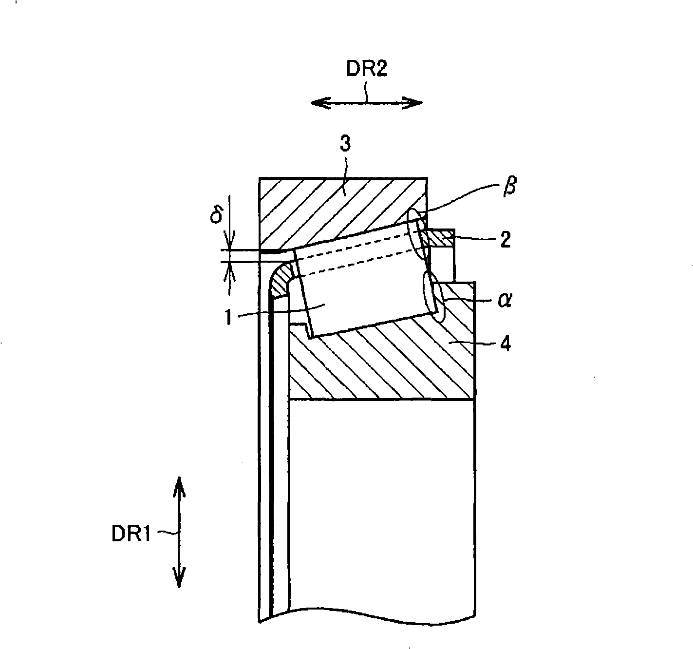
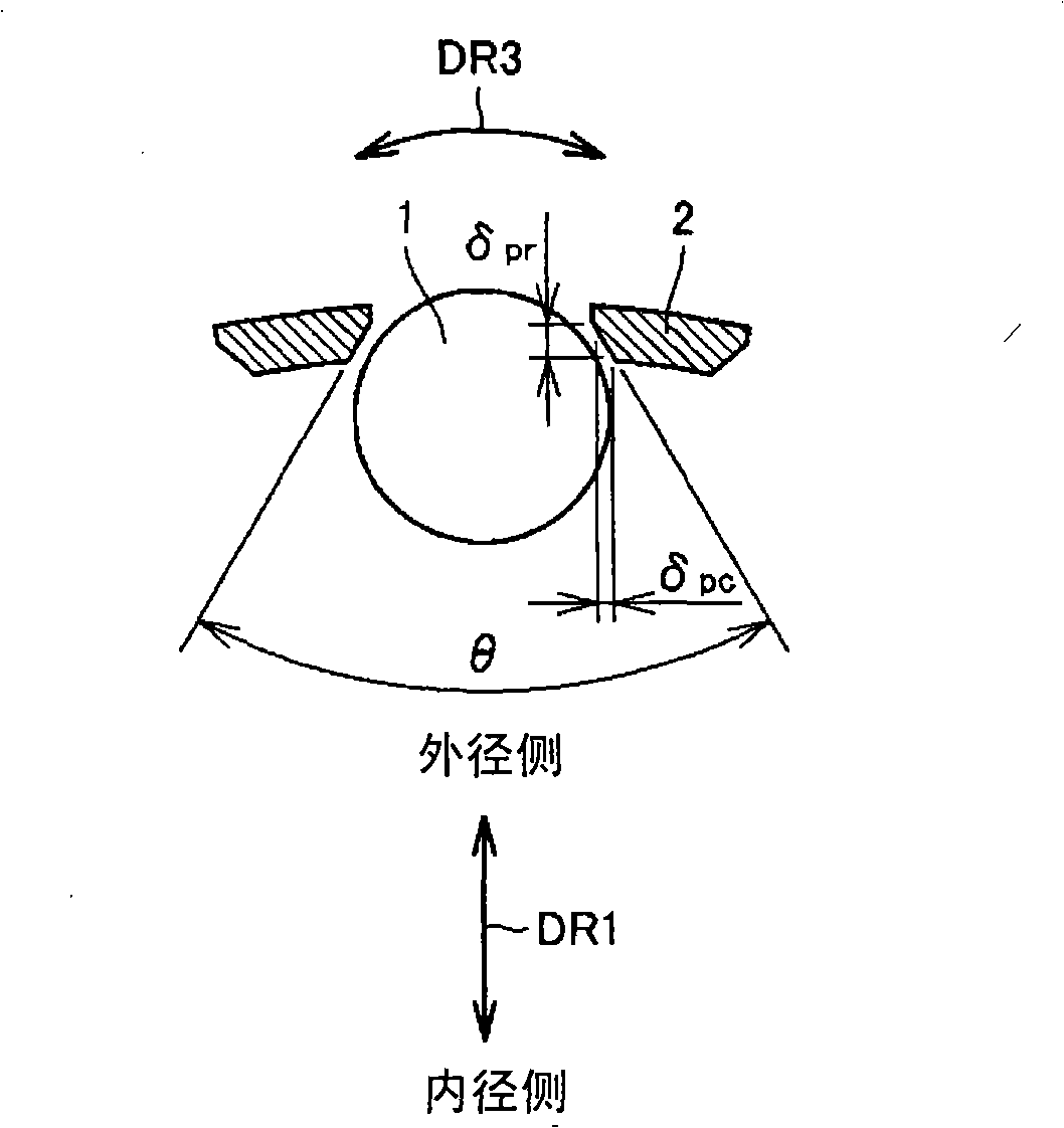
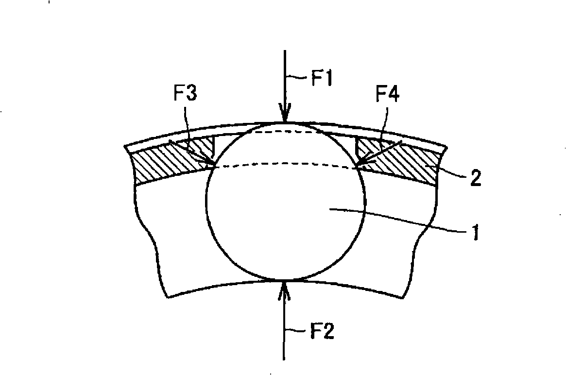
[0031] figure 1 It is a sectional view showing the tapered roller bearing according to Embodiment 1 of the present invention. exist figure 1 Among them, the arrow DR1 indicates the radial direction of the bearing, and the arrow DR2 indicates the axial direction of the bearing. refer to figure 1 , The tapered roller bearing of this embodiment includes: a roller 1 as a "rolling element", a cage 2 with a pocket for holding the roller 1, and an outer ring 3 and an inner ring as a "raceway ring". 4. Roller 1 rolls between outer ring 3 and inner ring 4 . The cage 2 is formed of, for example, iron. The cage 2 is disposed near the outer ring 3 .

[0032] exist figure 1 middle,

[0033] (A) The rolling surface of the roller 1 is in contact with the ...


PUM


Abstract

A tapered roller bearing having raceway rings including an inner ring (4) and an outer ring (3), rollers (1) rolling between the inner ring (4) and the outer ring (3), and a retainer (2) having pockets for retaining the rollers (1) and positioned near the outer ring (3). The bearing satisfies deltapr > deltapc and simultaneously -2 <=(delta - deltapr)/(deltapr - deltapc) <= 0, where delta is a radial clearance between the retainer (2) and the outer ring (3) when the retainer (2) is at a neutral position, dpris a radial clearance between a roller (1) retained in a pocket and the retainer (2), and deltapc is a circumferential clearance between the roller (1) retained in the pocket and the retainer (2).

Description

technical field [0001] The present invention relates to a tapered roller bearing, in particular to a tapered roller bearing which allows the cage to be in contact with the raceway surface. Background technique [0002] In the field of rolling bearings, as a method of increasing the load capacity, generally, the number of rolling elements is increased. When the number of rolling elements is increased, the circumferential intervals of the rolling elements become narrower. In contrast, by enlarging the diameter of the cage to relatively increase the circumferential width of the cage, the rigidity of the cage can be ensured. Therefore, from the viewpoint of increasing the rigidity of the cage, it is desirable to minimize the gap between the cage and the raceway surface (outer ring / inner ring). [0003] As a bearing that allows the cage to contact the raceway surface of the outer ring during operation, there is, for example, the bearing described in Japanese Patent Application ...

Claims


Application Information

Patent Timeline
Patent Type & Authority Applications(China)
IPC IPC(8): F16C33/46F16C19/36F16C33/56
CPCF16C19/364F16C33/4617F16C33/4676F16C33/543F16C2300/02
Inventor 原田和庆坂口智也
Owner NTN CORP
Why Eureka
Try Eureka