Elastic member for pushbutton switch

A technology of elastic parts and switches, which is applied to electric switches, electrical components, key modules, etc., can solve the problems that elastic parts cannot have a stroke S1, it is difficult to adjust the peak stroke, and the pressing part cannot maintain the shape, etc.

Inactive Publication Date: 2008-10-29
POLYMATECH CO LTD
View PDF1 Cites 11 Cited by
  • Summary
  • Abstract
  • Description
  • Claims
  • Application Information

AI Technical Summary

Problems solved by technology

[0006] However, as described in Patent Document 1, when the elastic member having the annular protrusion at the top is pressed, it is necessary to further satisfy the requirement (1), because in the case where the elastic member is assembled in the push button switch in a pre-compressed state , the ring-shaped protrusion has been deformed in the initial state, so sometimes the pressing part cannot maintain its shape
Therefore, the elastic part may not get the desired stroke S1, and it may be difficult to adjust the peak stroke
Furthermore, after the connection is completed, the annular protrusion expected to be elastically deformed has already been deformed, and therefore, the desired increase in the springback load may not be obtained.

Method used


Image

  • Elastic member for pushbutton switch
  • Elastic member for pushbutton switch
  • Elastic member for pushbutton switch

Examples


no. 1 example

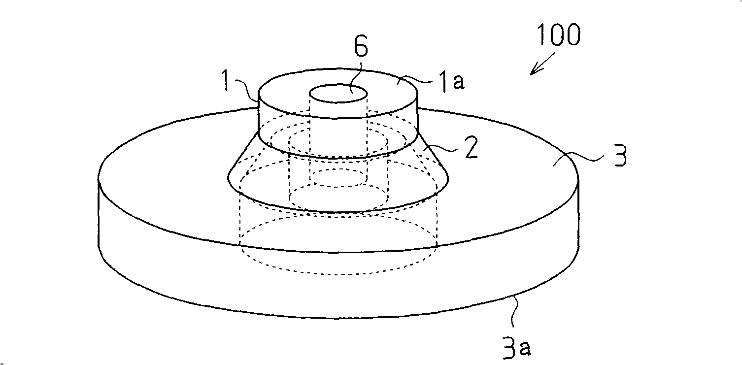
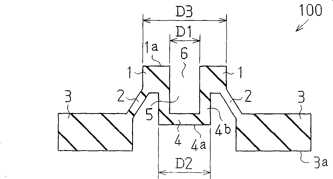
[0033] figure 2 and image 3 are a perspective view and a longitudinal sectional view respectively showing the elastic member 100 according to the first embodiment of the present invention.

[0034] The elastic member 100 has an annular flat base 3 , a thin connecting portion 2 extending obliquely upward from the inner circumference of the base 3 , and a substantially disk-shaped pressing portion 1 supported by the connecting portion 2 above the base 3 . According to this embodiment, if figure 2 As shown, the connecting portion 2 is shaped like an inverted funnel (truncated cone) and converges upwards. The pressing part 1 has a protrusion protruding downward from the lower surface of the pressing part 1 , that is, a push rod 4 . The lower surface 4 a of the push rod 4 is located above the lower surface 3 a of the base 3 . A hollow portion 5 is created inside the push rod 4 , and an opening portion 6 continuing from the hollow portion 5 of the push rod 4 is generated insi...

no. 2 example

[0047] Figure 7 is a perspective view showing an elastic member 200 according to a second embodiment of the present invention.

[0048] The elastic member 200 has a pair of prism-shaped bases 3 spaced apart from each other, thin-plate-shaped connecting parts 2 extending obliquely upward from opposite upper ends of the two bases 3 , and a rectangular plate supported by the connecting part 2 above the bases 3 shaped pressing part 1. The pressing part 1 has a substantially prismatic push rod 4 protruding downward from the lower surface of the pressing part 1 . The lower surface 4 a of the push rod 4 is located above the lower surface 3 a of the base 3 . A hollow portion 5 having openings on both sides of the push rod 4 is formed in the push rod 4 .

no. 3 example

[0050] Figure 8 is a perspective view showing an elastic member 300 according to a third embodiment of the present invention.

[0051] The elastic member 300 has the same structure as the elastic member 200 except that an opening 6 continuing from the hollow portion 5 of the push rod 4 is formed on the upper surface 1 a of the pressing portion 1 . The hollow part 5 of the push rod 4 and the opening part 6 of the pressing part 1 have the same side cross-sectional shape. Such as Figure 8 As shown, the opening 6 of the pressing part 1 and the hollow part 5 of the push rod 4 make the pressing part 1 and the push rod 4 form a U shape as a whole.

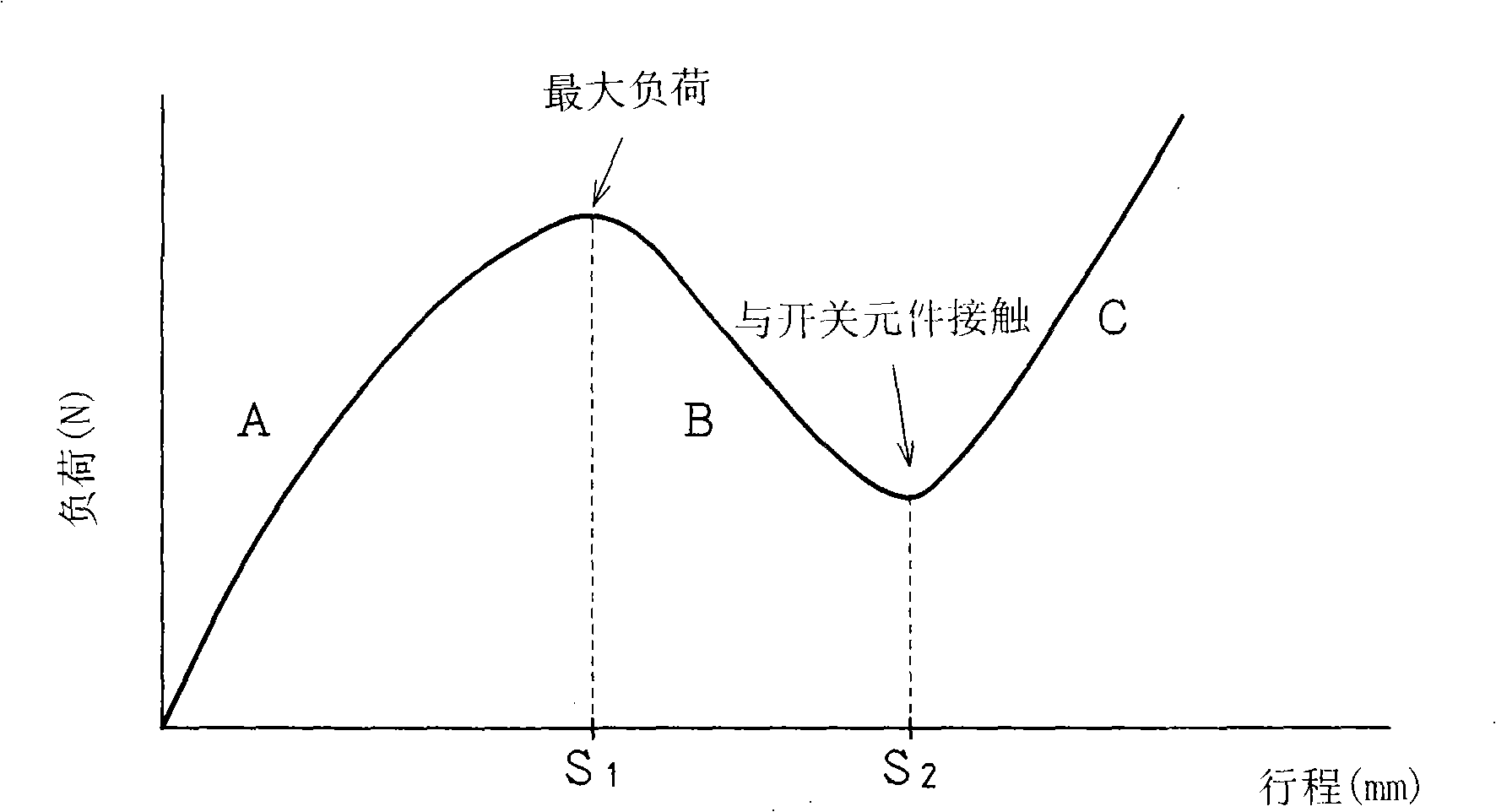
[0052] When the elastic member 200 or 300 is assembled in the structure of the button switch and used, when the pressing part 1 of the elastic member 200 or 300 is pressed, the connecting part 2 is elastically deformed and bent, so that the lower surface 4a of the push rod 4 is in contact with the The switching element (not shown) on...


PUM


Abstract

An elastic member for a pushbutton switch, providing soft tactile sensation to the operator when it is pushed down. The elastic material for a pushbutton switch has a base, a connection section extending from the base, a pressing section supported above the base by the connection section, and a projection section projecting downward from the pressing section. The inside of the projection section is hollow.

Description

technical field [0001] The present invention relates to an elastic member for a push button switch for performing input operations of electronic devices and the like. Background technique [0002] A conventional push button switch for performing an input operation of an electronic device or the like has an elastic member arranged under a key top. This elastic member provides an elastic return force against the operator when the button switch is pressed, and produces a click when the button moves a certain amount of travel. Such as Figure 9 As shown, this conventional elastic member has a base 3 , a connecting portion 2 extending obliquely upward from the base 3 , and a substantially disc-shaped pressing portion 1 supported by the connecting portion 2 above the base. The lower surface of the pressing part 1 has a protruding part called a push rod 4 for opening and closing the switching circuit by contacting a switching element (not shown) disposed on the switching circuit b...

Claims


Application Information

Patent Timeline
Patent Type & Authority Applications(China)
IPC IPC(8): H01H13/26H01H13/12H01H13/52
CPCH01H2227/022H01H13/85H01H2227/032H01H2233/102
Inventor 藤纲洋
Owner POLYMATECH CO LTD
Why Eureka
Try Eureka