Energy-saving electromagnet

A technology of electromagnets and iron plates, applied in the direction of electromagnets, etc., can solve problems such as the shortage of copper wire resources, affect the reaction speed, pollution, etc., achieve the effects of improving ventilation and heat dissipation conditions, solving slow movement speed, and reducing costs

Inactive Publication Date: 2008-11-05
张家政
View PDF0 Cites 1 Cited by
  • Summary
  • Abstract
  • Description
  • Claims
  • Application Information

AI Technical Summary

Problems solved by technology

[0002] In the existing energy-saving electromagnet, the material of the coil is copper wire, and the material of the shell is cast steel; copper wire resources are in short supply and expensive
The processing of cast steel workpieces is produced by manual single-piece production, which has high labor intensity, poor working conditions, low efficiency, large processing volume, high cost, and serious pollution in the production process of steel castings.
[0003] In addition, the housings of the existing energy-saving electromagnets are closed housings, and the short-circuit ring formed by the closed housings will easily cause the electromagnet to slow down and affect the reaction speed.

Method used


Image

  • Energy-saving electromagnet
  • Energy-saving electromagnet
  • Energy-saving electromagnet

Examples


Embodiment 1

[0022] Embodiment 1 (see figure 1 , 2 ):

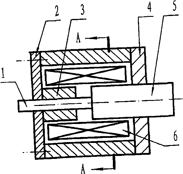
[0023] Depend on figure 1 , 2 It can be seen from the shown embodiment 1 that it includes a coil 6, an armature 5, a forehead iron 3, an upper cover 4, and a bottom plate 2; the characteristic is that the material of the coil 6 is aluminum wire.

[0024] The material of the upper cover 4 and the bottom plate 2 is iron plate.

[0025] The housing is a first circular tubular housing 7 with an axial through-slot hole 8, one end of the first circular tubular housing 7 is welded to the upper cover 4, and the other end is fixedly connected to the bottom plate 2 with screws ; The material of the first circular tubular shell 7 is iron pipe.

[0026] exist figure 1 Middle 1 is a push rod, and 9 is a mounting hole located on the base plate 2.

Embodiment 2

[0027] Embodiment 2 (see figure 1 , 3 ):

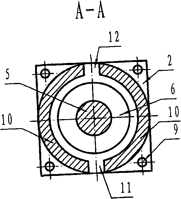
[0028] The difference between Embodiment 2 and Embodiment 1 is that the housing is a second circular tubular housing 10 with a pair of symmetrical axial through-slot holes 11 and 12 composed of two semicircular tubes. One end of the casing 10 is welded to the upper cover 4 , and the other end is fixedly connected to the bottom plate 2 with screws; the material of the second circular tubular casing 10 is iron pipe.

Embodiment 3

[0029] Embodiment 3 (see figure 1 , 4 ):

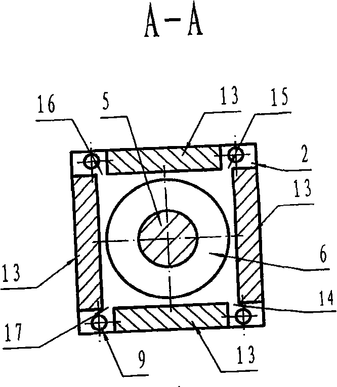
[0030] The difference between embodiment 3 and embodiment 1 is that the housing is a square tubular housing 13 composed of four iron plates, and the four edges of the square tubular housing 13 are respectively provided with first and second , the 3rd, the 4th gap 14,15,16,17, promptly be provided with gap between the adjacent sides of described four iron plates; One end of described four iron plates is welded with loam cake 4, and their other One end is respectively fixedly connected with the bottom plate 2 with screws.


PUM


Abstract

The invention relates to an energy saving electromagnet, including a coil, an armature, a front iron, an upper cover, a base plate, characterized in that, the coil is made of aluminum wires, wherein the upper cover and the base plate are made of iron plate. An axial continuous manger hole or an axial clearance is arranged on the case. The invention has the beneficial effect that: (1) the electromagnet coil of the invention adopts the aluminum wire to replace the copper wire, which greatly reduces the cost; (2) axial continuous manger hole or an axial clearance is arranged on the case which avoids the formation of the short circuit ring, thereby solving the problems of slow action speed caused by the short circuit ring of the case; (3) the iron plate and the iron pipe replace the base plate, the upper cover and the case made of the cat steel, thereby avoiding the pollution in the production process; (4) an axial continuous manger hole or an axial clearance is arranged on the case, which improves the ventilation heat dissipation conditions, reduces the failure by overheat.

Description

technical field [0001] The invention relates to an energy-saving electromagnet. Background technique [0002] In the existing energy-saving electromagnet, the material of the coil is copper wire, and the material of the shell is cast steel; copper wire resources are in short supply and expensive. The processing of cast steel workpieces is produced by manual single-piece production, which has high labor intensity, poor working conditions, low efficiency, large processing volume, high cost, and serious pollution in the production process of steel castings. [0003] In addition, the housings of existing energy-saving electromagnets are all closed housings, and the short-circuit ring formed by the closed housings will easily cause the electromagnet to slow down and affect the reaction speed. Contents of the invention [0004] The technical problem to be solved by the present invention is to provide an energy-saving electromagnet with low cost and fast action speed. [0005] ...

Claims


Application Information

Patent Timeline
Patent Type & Authority Applications(China)
IPC IPC(8): H01F7/06
Inventor 张利张旗张家政
Owner 张家政
Why Eureka
Try Eureka