
A turbine driven electric power production system and a method for control thereof

A technology of turbines and transmission systems, applied in the control of wind turbines, machines/engines, engines, etc., to achieve the effect of improving accuracy and avoiding instability

Inactive Publication Date: 2008-11-05
CHAPDRIVE AS
View PDF9 Cites 18 Cited by
  • Summary
  • Abstract
  • Description
  • Claims
  • Application Information

AI Technical Summary

Problems solved by technology

However, as mentioned in the background, the proposed system has many disadvantages

Method used


Image

  • A turbine driven electric power production system and a method for control thereof
  • A turbine driven electric power production system and a method for control thereof
  • A turbine driven electric power production system and a method for control thereof

Examples


Embodiment Construction

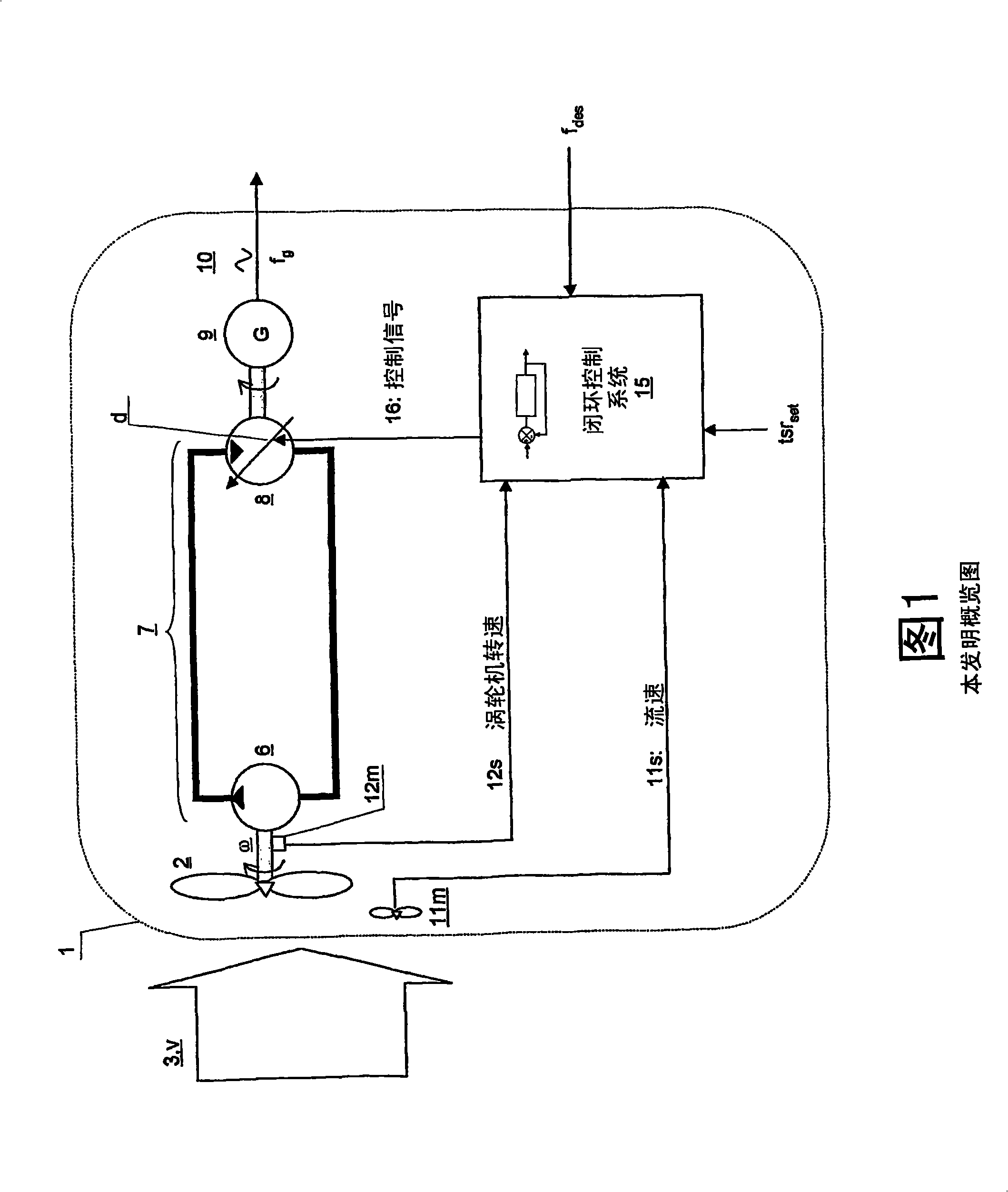
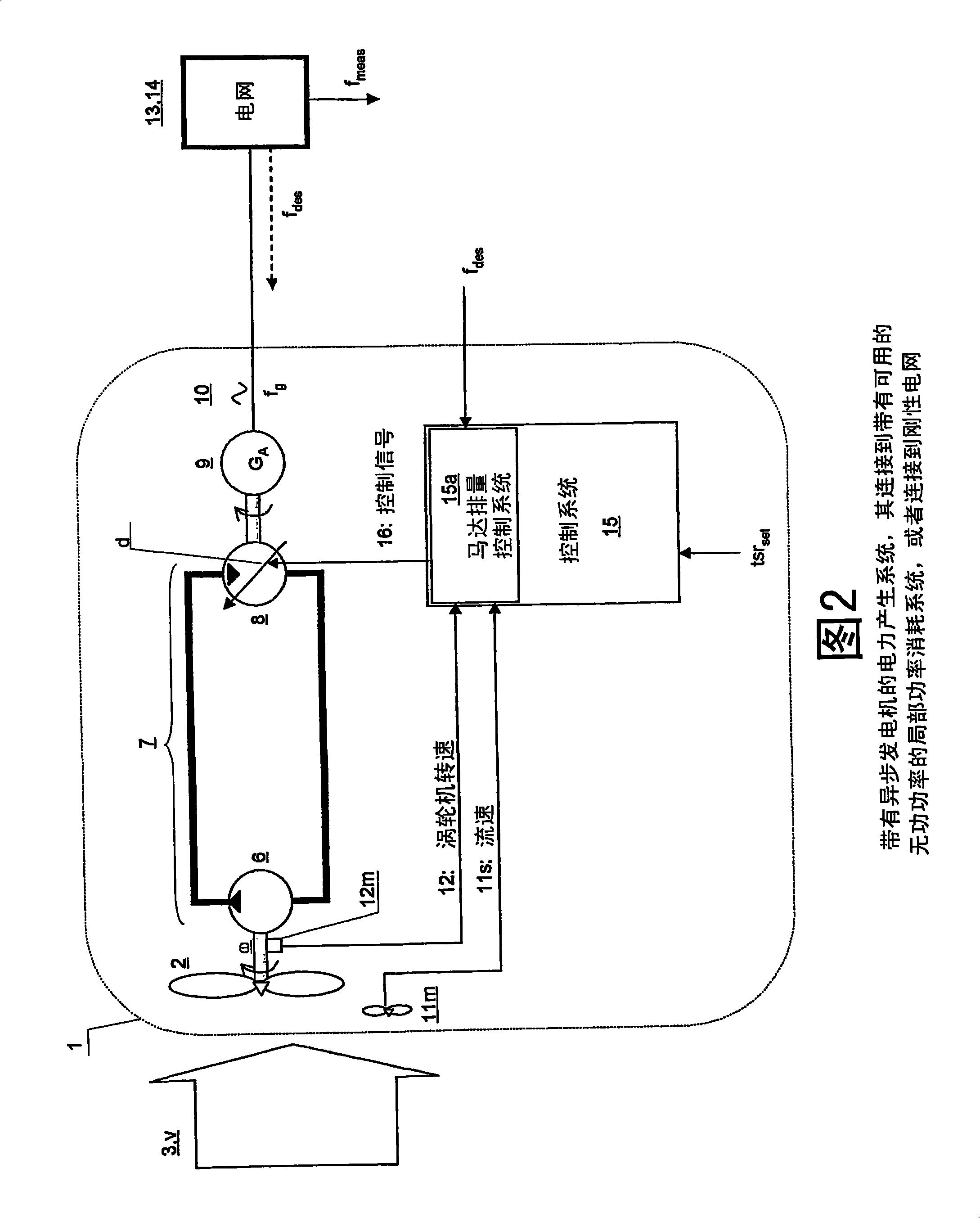
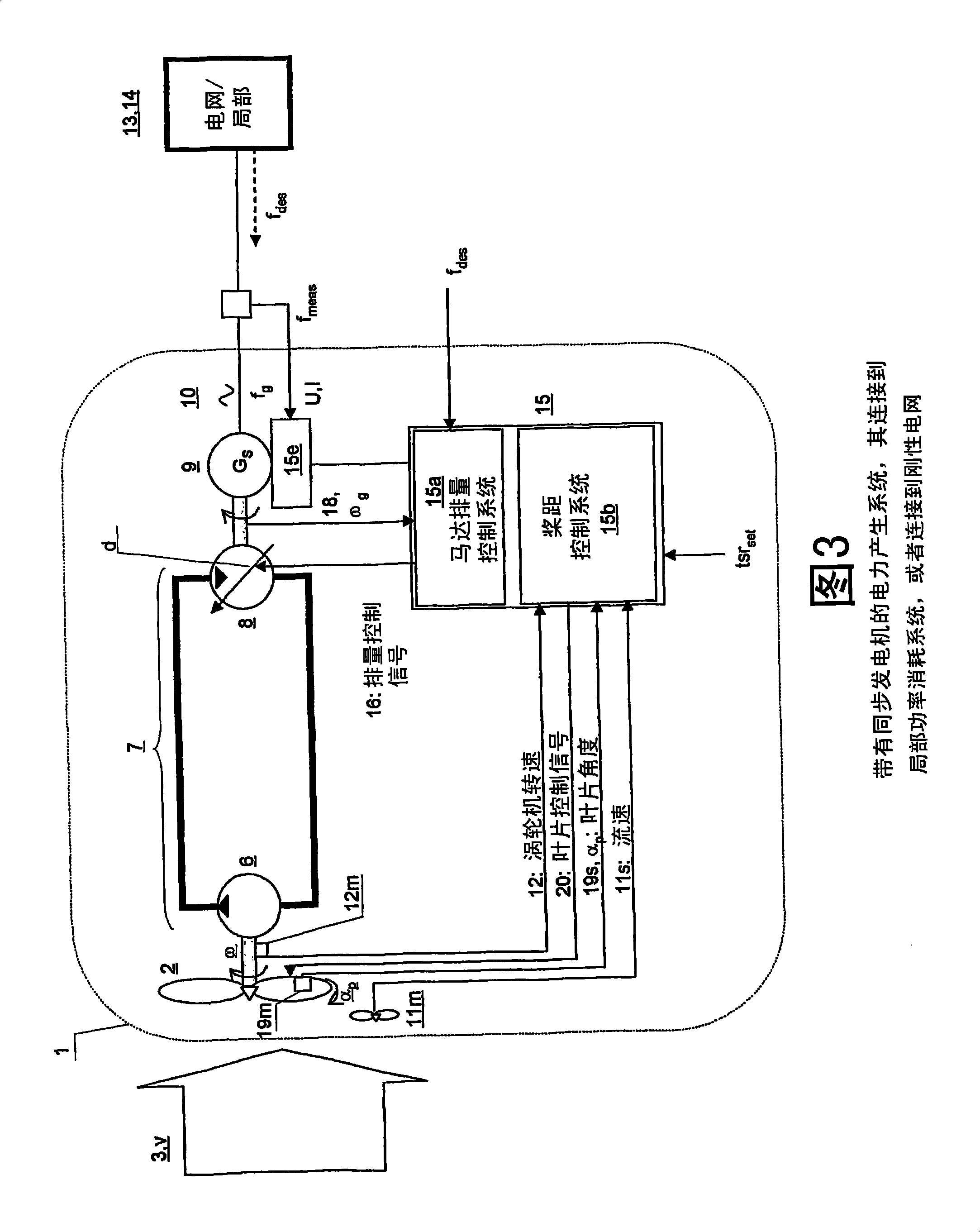
[0051] The invention comprises a turbine driven power generation system (1). The turbine (2) is arranged to be driven by a fluid (3) having a time-varying flow velocity (v), such as is the case with a wind turbine or a water turbine. In the following description, only examples involving wind turbines are discussed, however, it will be apparent to a person skilled in the art that the invention is equally applicable to water driven turbines. Referring to Figure 1, the turbine (2) is connected to operate the hydrostatic displacement pump (6), which is further connected to the hydrostatic displacement motor (8) which is part of the hydrostatic transmission system (7) ). The hydrostatic system may be a closed loop hydrostatic system or an open loop hydrostatic system. The hydrostatic motor (8) is arranged to transmit rotational torque by connecting the hydrostatic motor (8) to a rotating shaft of a generator (9) supplied with alternating current (10). Usually required to stabili...


PUM


Abstract

A turbine (2) driven electric power production system (1), - said turbine (2) arranged for being driven by a fluid (3) having a fluid speed (v) varying in time, - said turbine (2) connected to a hydrostatic displacement pump (6) further connected to a hydrostatic displacement motor (8) as part of a closed loop hydrostatic transmission system (7), - said motor (8) arranged for driving an electrical generator (9) supplying AC power (10) at a frequency (fg) near a given desired frequency (fdes), characterized by a closed loop system arranged for controlling a volumetric displacement (13) of the hydrostatic motor (8), comprising - a fluid speed meter (11m) arranged for producing a speed signal (11s) representing a speed (v) of said fluid (3), and - a rotational speed meter (12m) arranged for providing a rotational speed signal (12s) representing a rotational speed measurement (); of said turbine (2), - a motor displacement control system (15) for continuously receiving said speed signal (11s) and said rotational speed signal (12s) and arranged for calculating a control signal (16), - a volumetric displacement control actuator (17) on said hydrostatic motor, arranged for receiving said control signal (16) for continuously adjusting a volumetric displacement (d) of said hydrostatic motor (8) for maintaining a set turbine tip speed ratio (tsrset) and thereby providing an improved power efficiency of the power production system (1) during fluctuations in said fluid speed (v).

Description

technical field [0001] The present invention relates to a turbine driving power generation system and its control system. More specifically, the present invention relates to a turbine in a power generation system driven by a fluid whose flow rate varies with time, the turbine driving a hydrostatic displacement pump being connected to a hydrostatic displacement pump in a hydrostatic transmission system The displacement motor, the hydrostatic displacement motor, further drives a generator, providing alternating current (AC) electricity at a frequency close to a given desired frequency. Flow rate measurements, turbine speed measurements, and hydrostatic motor or generator speed measurements can be used as inputs to a motor displacement control system to calculate control signals for controlling the volumetric displacement of the hydrostatic motor. Background technique [0002] Typically, power from a wind turbine system is transferred mechanically, either directly to the gener...

Claims


Application Information

Patent Timeline
IPC IPC(8): F03D7/00F16H
CPCY02E10/722Y02E10/723Y02E10/72
Inventor P·查普尔O·G·达尔豪格P·O·哈贝格
Owner CHAPDRIVE AS
Learn More