
Fuel high pressure generating apparatus of direct spray petrol engine in cylinder

A technology for generating devices and gasoline engines, applied to liquid fuel feeders, charging systems, mechanical equipment, etc., can solve problems such as low reliability, pressure fluctuations, corrosion, etc., to improve system reliability, fuel supply The effect of pressure stabilization

Inactive Publication Date: 2008-11-12
ZHEJIANG UNIV
View PDF1 Cites 0 Cited by
  • Summary
  • Abstract
  • Description
  • Claims
  • Application Information

AI Technical Summary

Problems solved by technology

The high-pressure generating device is the most critical part of the direct injection engine fuel supply system. The traditional pressure generating device generally uses the engine to drive the plunger oil pump to generate high-pressure fuel. Due to the high-precision cooperation of the plunger couple, they work In a state of high-speed motion, good lubrication is required to prevent wear, but gasoline and other fuels have poor lubricity and even corrosion, so the reliability of traditional methods is not high
[0003] There is also the technology introduced in patent 200410067003, which uses two hydraulic cylinders to alternately supply oil to provide the high-pressure oil required for fuel injection. The disadvantage of this technology is that when the two cylinders work alternately, certain pressure fluctuations

Method used


Image

  • Fuel high pressure generating apparatus of direct spray petrol engine in cylinder
  • Fuel high pressure generating apparatus of direct spray petrol engine in cylinder
  • Fuel high pressure generating apparatus of direct spray petrol engine in cylinder

Examples


Embodiment Construction

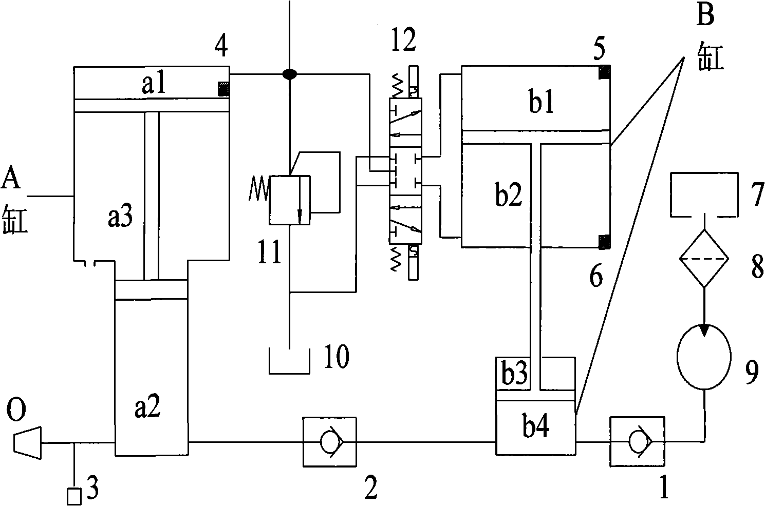
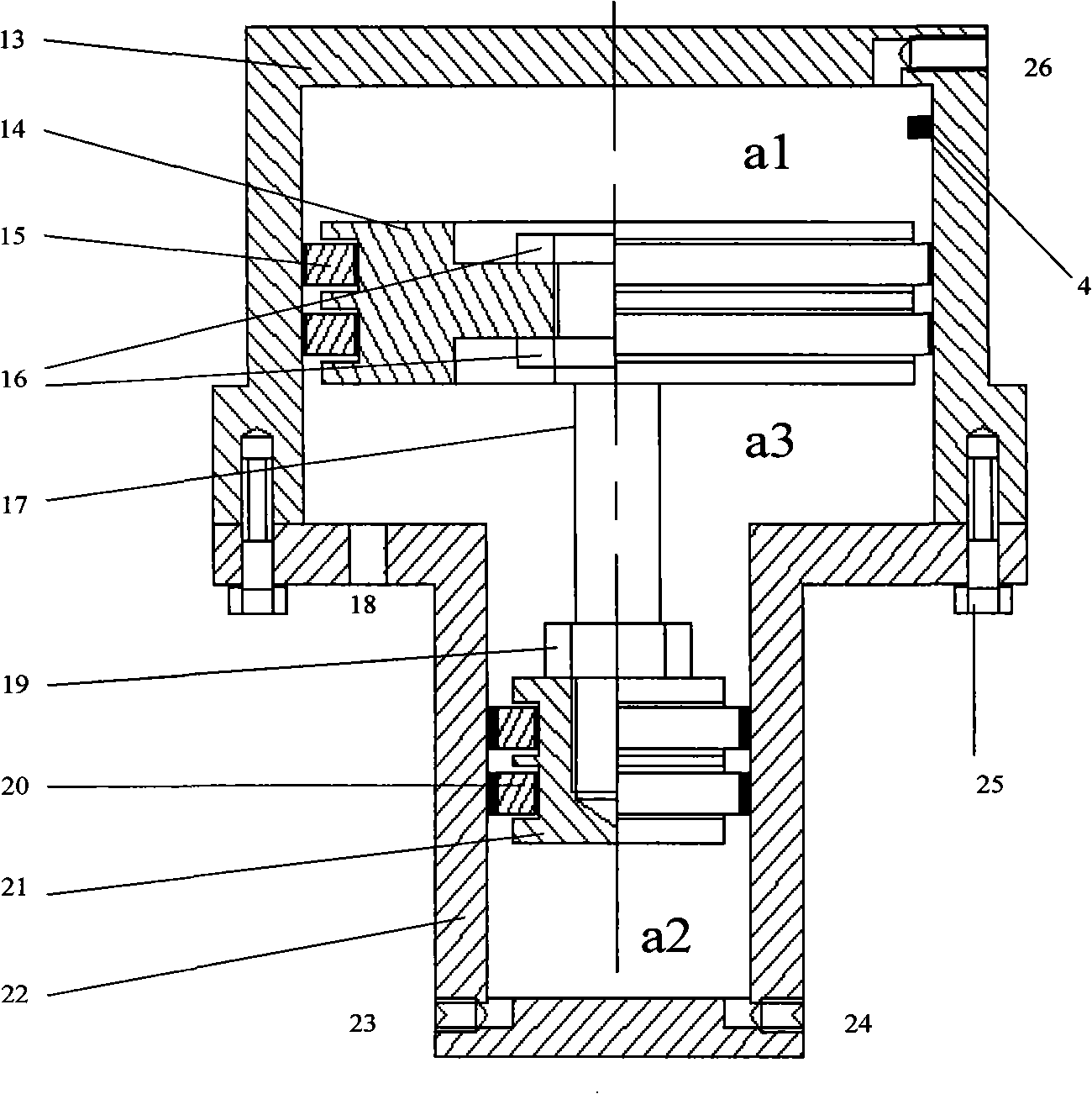
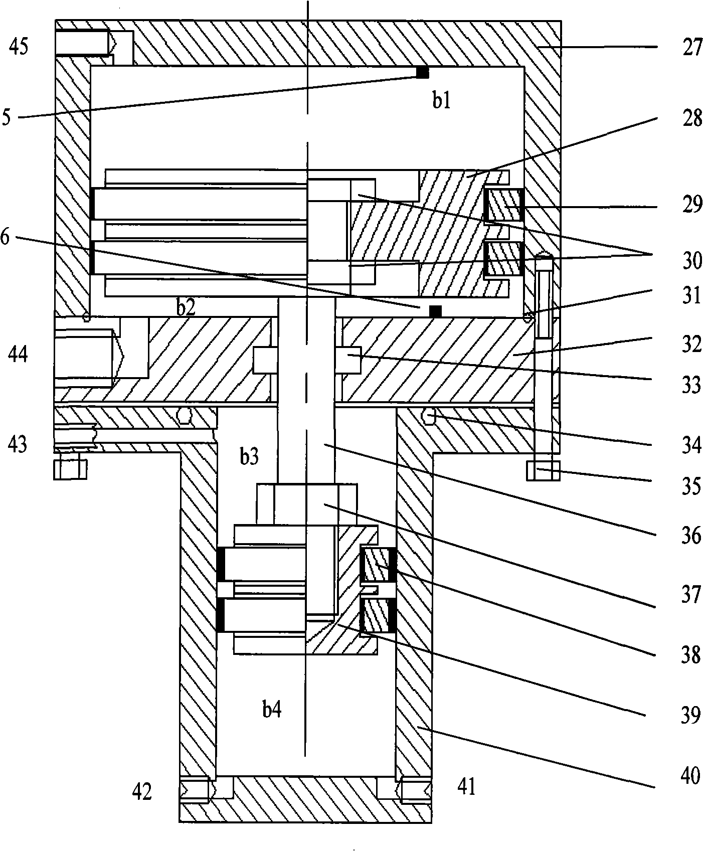
[0018] like figure 1 As shown, the fuel high-pressure generating device for direct injection in the gasoline engine cylinder has an oil storage cylinder A and a fuel supply cylinder B, and the second fuel input hole 41 of the fuel supply cylinder B is sequentially connected in series with a first check valve 1 and a fuel delivery pump. 9. Fuel filter 8, fuel tank 7, a second check valve 2 is connected in series between the second fuel output hole 42 of fuel supply cylinder B and the first fuel input hole 24 of fuel supply cylinder A. The pressure sensor 3 is connected to the first fuel output hole 23 of the cylinder, and the second working oil inlet and outlet hole 44 and the third working oil inlet and outlet hole 45 of the fuel supply cylinder B are connected to the electro-hydraulic reversing valve 12, and the electro-hydraulic reversing valve 12 The overflow valve 11 is connected to the first working oil inlet and outlet hole 26 of cylinder A of the oil storage cylinder. T...


PUM


Abstract

The invention discloses a device for producing high pressure to directly spray fuel in a gasoline motor cylinder. The device is provided with an oil storage tank A and an oil supply tank B, wherein, a cavity b4 of the oil supply tank B is successively connected with a first one-way valve, a fuel transfer pump, a fuel filter, and a fuel tank in series; the cavity a2 of the oil supply tank A is connected with a pressure sensor 3; a second one-way valve is connected between the cavity b4 of the oil supply tank B and the cavity a2 of the oil supply tank A in series; the cavity b1 and the cavity b2 of the oil supply tank B are connected with a electro-hydraulic change-over valve connected with the cavity a1 of the oil storage tank A by an overflow valve; a first position sensor is arranged in the cavity a1 of the oil storage tank A; a second position sensor and a third position sensor are respectively arranged in the cavity b1 and the cavity b2 of the oil supply tank B. The device is easy to realize high pressure boosting of the fuel and is applicable to a plurality of liquid and gaseous fuels; the device solves the sealing problem of fuels with low viscosity and lubrication; by adopting separate oil storage tank, the pressure for supplying the oil can be stable without a pressure accumulating device.

Description

technical field [0001] The invention relates to a fuel high-pressure generating device for direct injection in a gasoline engine cylinder. Mainly used in engine fuel injection system, the purpose is to provide stable and high enough fuel injection pressure. Background technique [0002] Gasoline engine direct injection technology has changed the traditional gasoline engine oil-air mixing mechanism and can greatly improve fuel economy. It has become an important direction of internal combustion engine research. The high-pressure generating device is the most critical part of the direct injection engine fuel supply system. The traditional pressure generating device generally uses the engine to drive the plunger oil pump to generate high-pressure fuel. Due to the high-precision cooperation of the plunger couple, they work In a state of high-speed motion, good lubrication is required to prevent wear, but gasoline and other fuels have poor lubricity and even corrosion, so the re...

Claims


Application Information

Patent Timeline
Patent Type & Authority Applications(China)
IPC IPC(8): F02M37/04
Inventor 何文华田素恒刘建军
Owner ZHEJIANG UNIV
Learn More