Fuel high pressure generator for oil supply system with direct jetting of liquefied petroleum gas/petrol in cylinder

A gasoline direct injection and liquefied petroleum gas technology, which is applied to liquid fuel feeders, charging systems, machines/engines, etc., can solve problems such as poor sealing performance, reduced matching accuracy of plunger couplings, and device failure. , to stabilize the fuel injection pressure and improve the reliability of the system

A gasoline direct injection and liquefied petroleum gas technology, which is applied to liquid fuel feeders, charging systems, machines/engines, etc., can solve problems such as poor sealing performance, reduced matching accuracy of plunger couplings, and device failure. , to stabilize the fuel injection pressure and improve the reliability of the system

CN100344868CInactive Publication Date: 2007-10-24ZHEJIANG UNIV

Image

  • Fuel high pressure generator for oil supply system with direct jetting of liquefied petroleum gas/petrol in cylinder
  • Fuel high pressure generator for oil supply system with direct jetting of liquefied petroleum gas/petrol in cylinder

Examples


Embodiment Construction

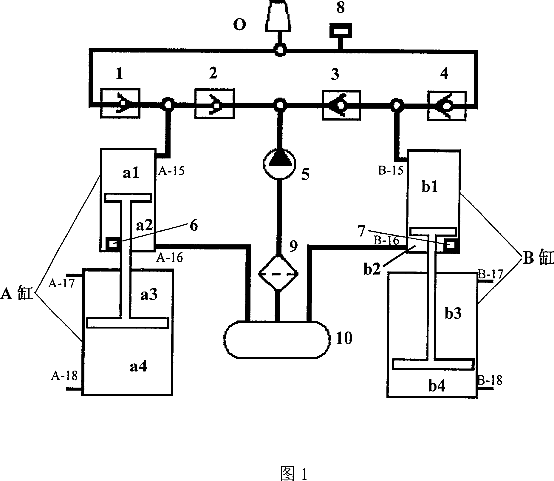
[0013] As shown in Figure 1, the fuel high-pressure generator of LPG (liquefied petroleum gas) / gasoline engine cylinder direct injection oil supply system, fuel filter 9, fuel delivery pump 5, on the fuel delivery pump 5 successively connect with first One-way valve 2, second one-way valve 1, pressure sensor 8, third one-way valve 4, fourth one-way valve 3, the connection point between the first one-way valve 2 and the second one-way valve 1 and the fuel pressure increaser The upper end a1 cavity of the first cylinder A of the pressure device is connected, and the connection point of the third check valve 4 and the fourth check valve 3 is connected with the b1 cavity at the upper end of the second cylinder B of the fuel pressure booster device; in the fuel pressure booster device A fuel compression cylinder position sensor 6 is installed in the a2 cavity of the first cylinder A, and a fuel compression cylinder position sensor 7 is installed in the b2 cavity of the second cylind...


PUM


Abstract

The high fuel pressure generator for oil supply system of directly jetting liquefied petroleum gas / petrol in cylinder includes fuel tank, fuel filter, fuel conveying pump, the first non-return valve, the second non-return valve, pressure sensor, the third non-return valve, the fourth non-return valve, and fuel pressure unit with cylinder A and cylinder B possessing fuel compressing cylinder position sensors. The present invention can realize high pressure of fuel easily, has no high speed moving part and raised system reliability and is suitable for pressurizing various kinds of liquid and gas fuel. It has two fuel compressing cylinders operating alternately to ensure stable fuel oil pressure without needing pressure accumulator.

Description

technical field [0001] The invention relates to a fuel high-pressure generating device of a liquefied petroleum gas / gasoline in-cylinder direct injection oil supply system. Background technique [0002] More and more direct injection technology in the engine cylinder has been applied to various medium and high-end cars, and it has become a main direction for the development of automobile technology in the future. The fuel high-pressure generating device is a key part of the direct injection fuel supply system in the engine cylinder. The traditional in-cylinder direct injection engine pressure generating device generally adopts the way that the engine drives the plunger type oil pump to press the oil to generate high-pressure fuel. There are many disadvantages in this high-pressure generating device: because the plunger coupling in the plunger oil pump adopts high-precision fit, and they are in a high-speed motion state when the plunger oil pump is working, this requires a go...

Claims


Application Information

Patent Timeline
24 Oct 2007
Publication
CN100344868C
IPC
F02M37/04; F02M37/22
Inventors
何文华; 邵千钧