Cylinder inside direct jet type engine fuel high pressure generator

An in-cylinder direct injection and generation device technology, applied in fuel injection devices, engine components, machines/engines, etc., can solve problems such as wear, impact on reliability, poor sealing performance, etc.

Inactive Publication Date: 2007-12-05
ZHEJIANG UNIV
View PDF8 Cites 0 Cited by
  • Summary
  • Abstract
  • Description
  • Claims
  • Application Information

AI Technical Summary

Problems solved by technology

The fuel high-pressure generating device is a key part of the direct injection fuel supply system in the engine cylinder. The traditional in-cylinder direct injection engine pressure generating device generally adopts the way that the engine drives the plunger type oil pump to press the oil to generate high-pressure fuel. This kind of high pressure generating device has many disadvantages: because the plunger coupling in the plunger oil pump adopts high-precision fit, and they are in a high-speed motion state when the plunger oil pump is working, this requires good communication between the plunger couplings. Lubrication to prevent parts from wear and tear, but for direct injection systems in engine cylinders that use fuels such as gasoline and liquefied petroleum gas, because gasoline, especially liquefied petroleum gas fuels have low viscosity and poor lubricity, if traditional In-cylinder direct-injection engine pressure generating device will inevitably lead to serious consequences of rapid wear of components and device failure. What's more, due to the corrosion of certain fuels, when using a plunger pump to pressurize, it will cause serious consequences due to the corrosion of the fuel. The matching accuracy of the plunger coupling is reduced, so that the traditional in-cylinder direct injection engine pressure generating device has problems such as difficult pressurization and poor sealing performance, which seriously affects the reliability of the system.

Method used


Image

  • Cylinder inside direct jet type engine fuel high pressure generator
  • Cylinder inside direct jet type engine fuel high pressure generator

Examples


Embodiment Construction

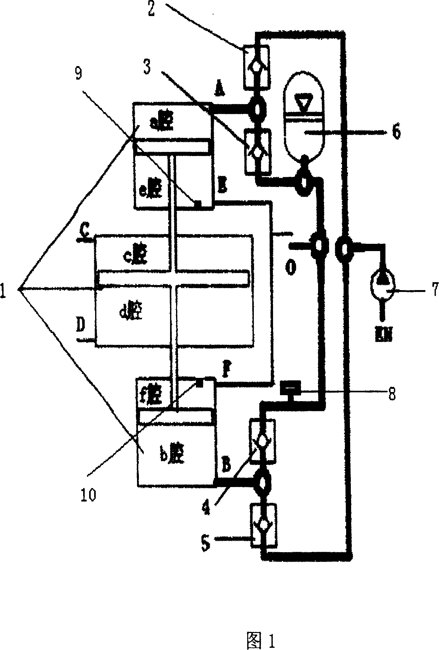
[0012] As shown in Figure 1, the fuel high-pressure generating device of an in-cylinder direct-injection engine has a fuel delivery pump 7, and a first check valve 2, a second check valve 3, and a pressure accumulator 6 are sequentially connected in series on the fuel delivery pump 7. , pressure sensor 8, the third one-way valve 4, the fourth one-way valve 5, the connection point of the first one-way valve 2 and the second one-way valve 3 is connected with the upper end of the fuel pressure booster 1, the third one-way valve The connection point between the valve 4 and the fourth one-way valve 5 is connected to the lower end of the fuel pressure booster 1, and the fuel pressure booster 1 is provided with an upper fuel compression cylinder position sensor 9 and a lower fuel compression cylinder position sensor 10 respectively.

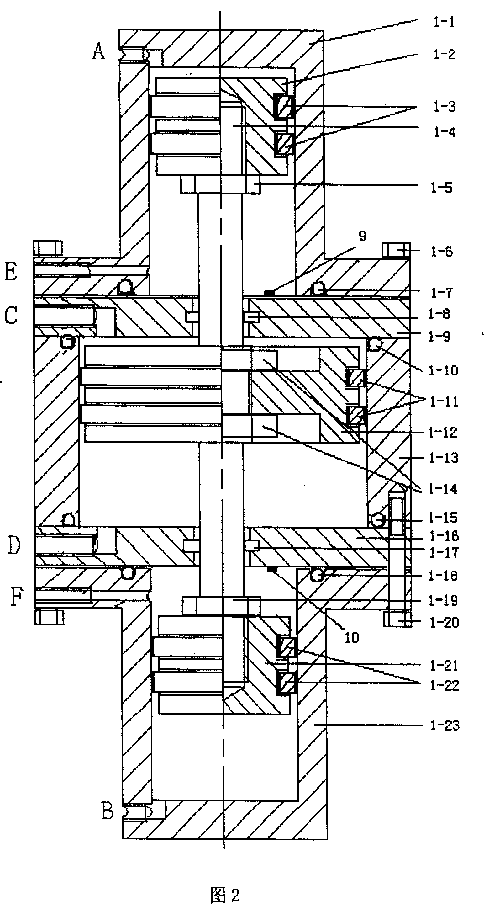
[0013] As shown in Figure 2, the fuel pressure booster device 1 sequentially has an upper fuel compression cylinder liner 1-1, a fluid power cylinder li...


PUM


Abstract

The invention discloses a kind of fuel high-pressure generator employed in straight spurting engine of inside vessel. The invention has a fuel convey pump, which is strung together the first one-way valve, the second one-way valve, storage voltage ware, pressure-sensor, the third one-way valve, the fourth one-way valve. The joining between the first noe-way valve and the second one-way valve links up the upper end of fuel pressure-raised device. The joining between the third one-way valve and the fourth one-way links up the lower end of fuel pressure-raised device. There are the pressure sensors of the location of the upper fuel compress vessel and the lower fuel compress vessel inside fuel pressure-raised device. There are merits of the invention 1) making high-pressure of fuel to raise easily 2) without parts of high speed working increasing stableness 3) resolving the problem of low viscosity and high-pressure airtight of low lubricating fuel 4) adapting to raising the pressure of many types of liquid and gas fuel.

Description

technical field [0001] The invention relates to an in-cylinder direct-injection engine fuel high-pressure generating device. Background technique [0002] More and more direct injection technology in the engine cylinder has been applied to various medium and high-end cars, and it has become a main direction for the development of automobile technology in the future. The fuel high-pressure generating device is a key part of the direct injection fuel supply system in the engine cylinder. The traditional in-cylinder direct injection engine pressure generating device generally adopts the way that the engine drives the plunger type oil pump to press the oil to generate high-pressure fuel. This kind of high pressure generating device has many disadvantages: because the plunger coupling in the plunger oil pump adopts high-precision fit, and they are in a high-speed motion state when the plunger oil pump is working, this requires good communication between the plunger couplings. Lu...

Claims


Application Information

Patent Timeline
Patent Type & Authority Patents(China)
IPC IPC(8): F02M47/02
Inventor 何文华邵千钧熊树生黄付强
Owner ZHEJIANG UNIV
Why Eureka
Try Eureka