Test device and test method of rapid response electronic device response speed

A technology for electronic devices and response speed, which is applied in the field of devices for testing the response speed of fast-response electronic devices, and can solve the problems of short response time of OLED screens, inability to observe and study carefully, and affecting measurement accuracy.

Active Publication Date: 2008-11-12
TSINGHUA UNIV +2
View PDF0 Cites 7 Cited by
  • Summary
  • Abstract
  • Description
  • Claims
  • Application Information

AI Technical Summary

Problems solved by technology

[0006] 1. Because the response time of the OLED screen is very short, a high-speed oscilloscope is required to observe the waveform, and the instrument cost is high;
[0007] 2. Such a fast waveform is fleeting on the oscilloscope, which cannot be carefully observed and studied, which affects the measurement accuracy;
[0008] 3. The response speed of the photoelectric sensing element, the time delay of the amplification and shaping circuit cannot be determined, and these factors will overwhelm or greatly affect the response speed of the OLED screen

Method used


Image

  • Test device and test method of rapid response electronic device response speed
  • Test device and test method of rapid response electronic device response speed
  • Test device and test method of rapid response electronic device response speed

Examples


Embodiment 1

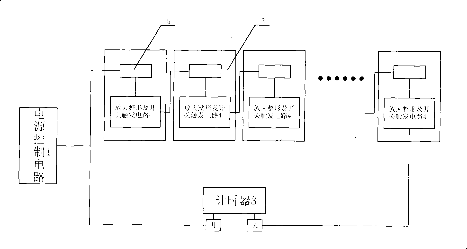
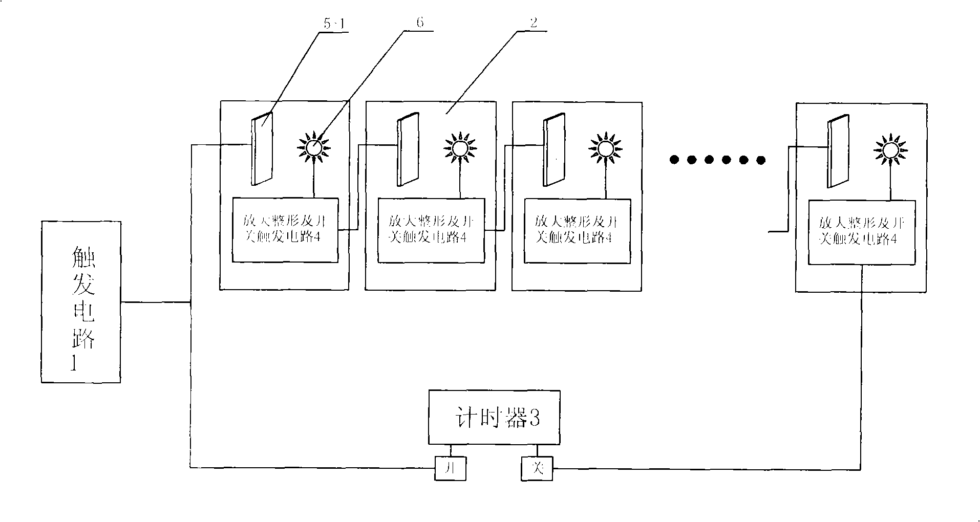
[0040] refer to figure 2 . The tested electronic device of this embodiment is an organic electroluminescence display device (OLED) 5-1, which is a photoelectric device, and the test needs to convert its response speed into an electrical signal, and increase the photoelectric sensor 6. At the same time, due to the output of the photoelectric sensor 6 The signal is weak, and its output signal terminal needs to be connected with the amplification shaping and switching trigger circuit 4, and the output terminal of this circuit triggers the response of the next group of OLED5-1. In this embodiment, 20 groups of OLED5-1 response modules are connected in series to test the overall response time. use as figure 2 test device. Proceed as follows:

[0041] (1) Measure the total response time T of 20 groups of response modules by using the test device. First, the power supply control circuit—trigger circuit 1 provides the same trigger signal to the first group of OLED response modu...

Embodiment 2

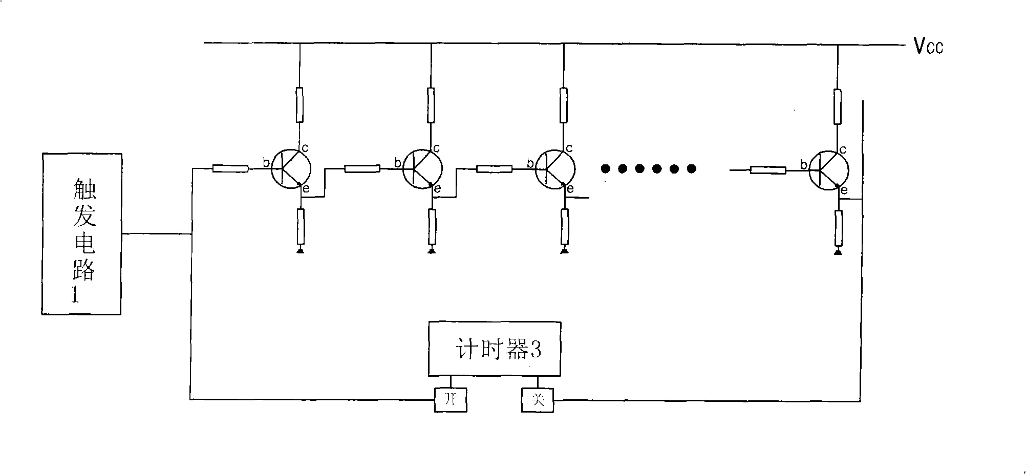
[0047] refer to image 3 . The tested electronic device of this embodiment is a triode 5-2, and the test does not need a sensor. In addition, because the triode emitter output signal is stronger and more stable, it is not necessary to add an amplification and shaping and switch trigger circuit 4 to connect, and the triode 5-2 The emitter e is directly connected to the base b of the next group of triodes 5-2 to be tested, and the signal of the emitter e of the last group of triodes 5-2 triggers the timer 3 to be turned off. In this embodiment, 20 sets of triode response modules 2 are connected in series to test the overall response time. use as image 3 test device.

[0048] Proceed as follows:

[0049] (1) Measure the total response time T of 20 groups of triode response modules 2 by using the test device. First, the triode 5-2 is set to a saturated state, and the same trigger signal is provided by the trigger circuit to the base b of the first group of triode response mo...


PUM


Abstract

The invention discloses a device for testing the response speed of quick response electronic devices and a testing method thereof. The device for testing the response speed of the invention comprises a power control circuit, at least two response modules of the electronic devices to be tested and a timer; the power control circuit is electrically connected with the power source end of the response modules; all modules are connected in series; the startup trigger signal of the timer synchronizes the trigger signal of the first response module; the shutoff trigger signal of the timer synchronizes the output signal of the last response module. The testing device and the testing method of the invention aim at overcoming the defects of the high cost and low measurement precision of the testing the response speed of the quick response electronic devices, measure the total response time by connecting a plurality of devices to be tested in series, obtain the response time of each group of devices by calculation, require no application of the display instruments of high cost and can obtain a high-precision testing result of electronic devices of the same type at the same time.

Description

technical field [0001] The invention relates to a test device and a test method thereof, in particular to a device for testing the response speed of fast-response electronic devices and a test method thereof. Background technique [0002] In recent years, with the rapid development of electronic devices such as semiconductors, the performance and response speed of various electronic devices have been greatly improved. Correspondingly, the device performance testing equipment is also developing rapidly. At present, the response speed of various fast-response electronic devices, such as high-performance photocoupler devices, has reached the nanometer level, and the test accuracy of the test equipment is far from meeting the requirements. The test work is only the result of rough tests, or Testing with expensive equipment costs a lot of money, and the cost is too high. [0003] In addition, organic electroluminescent displays (OLEDs), which have emerged in recent years, have a...

Claims


Application Information

Patent Timeline
Patent Type & Authority Applications(China)
IPC IPC(8): G01R31/00G01R31/26
Inventor 邱勇张柳青高裕弟应根裕
Owner TSINGHUA UNIV
Why Eureka
Try Eureka