
Reversing radar system with low aftershock and method for outputting reversing radar signal with low aftershock

A technology of reversing radar and aftershocks, applied in the field of low aftershock reversing radar systems, can solve the problems of inability to detect obstacles, the time increase of aftershocks, and the longer blind area of ​​reversing radar detection.

Inactive Publication Date: 2008-11-12
李世雄
View PDF0 Cites 8 Cited by
  • Summary
  • Abstract
  • Description
  • Claims
  • Application Information

AI Technical Summary

Problems solved by technology

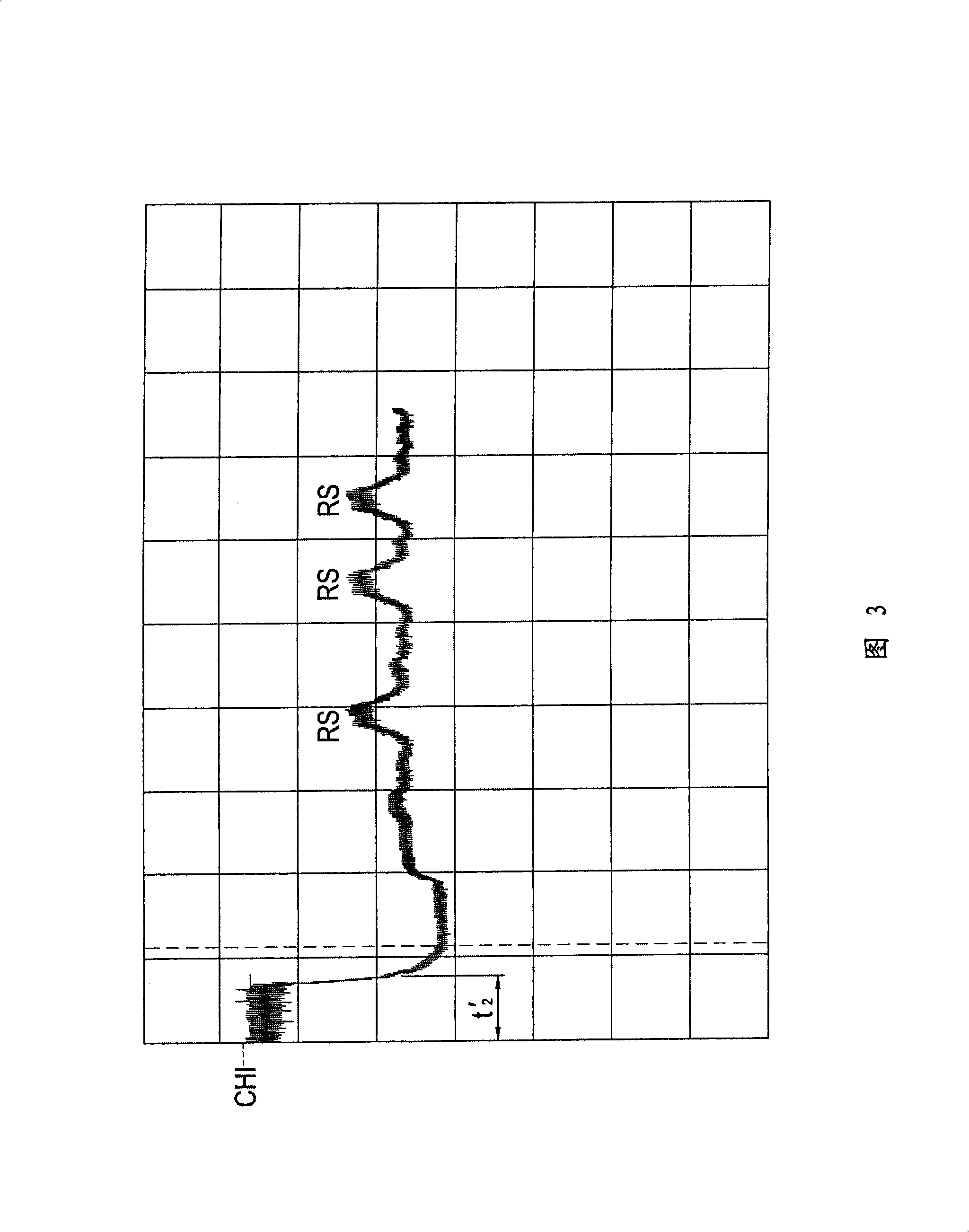
As shown in Figure 5, because the intensity of the aftershock interval t2 (amplitude of the t2 interval) of the piezoelectric ceramic sheet far exceeds the intensity (amplitude of RS) of the reflected ultrasonic signal RS, so in the aftershock interval t2, the reversing radar cannot detect obstacles
In addition, if the horizontal axis in Figure 4 represents time and each grid represents 2ms, it means that the aftershock interval t2 lasts about 2.4 milliseconds, during which the reversing radar cannot detect obstacles. s, that is to say, the reversing radar cannot give an alarm to obstacles within 40cm, and the range of 40cm is called the detection blind zone:
[0005] In addition, although a longer detection distance can be obtained by enhancing the transmission energy of the output ultrasonic wave, increasing the transmission energy of the output ultrasonic wave will increase the aftershock time, resulting in a longer detection blind zone of the reversing radar
However, in order to alleviate the aftershock phenomenon, the transmission energy of the output ultrasonic wave must be reduced, which sacrifices the effective detection distance
Generally speaking, the existing reversing radar with a detection blind zone less than 30cm has a detection distance of only about 1.2m, while the existing reversing radar with a detection distance greater than 1.8m has a detection blind zone of at least about 45cm; therefore , the aftershock phenomenon is actually one of the main reasons for the poor performance of the existing parking radar

Method used


Image

  • Reversing radar system with low aftershock and method for outputting reversing radar signal with low aftershock
  • Reversing radar system with low aftershock and method for outputting reversing radar signal with low aftershock
  • Reversing radar system with low aftershock and method for outputting reversing radar signal with low aftershock

Examples


Embodiment Construction

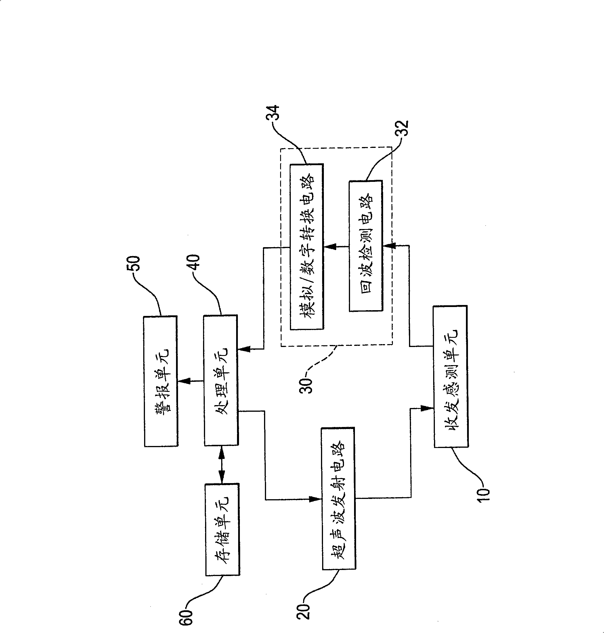
[0035] Such as figure 1 As shown, it is a preferred embodiment of the system for reducing the aftershock of the reversing radar of the present invention, which includes a transceiver sensing unit 10, an ultrasonic transmitting circuit 20, an ultrasonic receiving circuit 30, a processing unit 40, an alarm unit 50 and A storage unit 60 .

[0036] The sending and receiving sensing unit 10 is used as the sending and sensing of the reversing radar ultrasonic wave, and is usually composed of a plurality of ultrasonic sending and receiving sensors (SENSOR), and each ultrasonic sending and receiving sensor includes a piezoelectric ceramic sheet (not shown in the figure), The input of the transceiver sensing unit 10 is connected to the ultrasonic transmitting circuit 20, and the output of the transmitting and receiving sensing unit 10 is connected to the ultrasonic receiving circuit 30; the input of the ultrasonic transmitting circuit 20 is connected to the processing unit 40, and the ...


PUM


Abstract

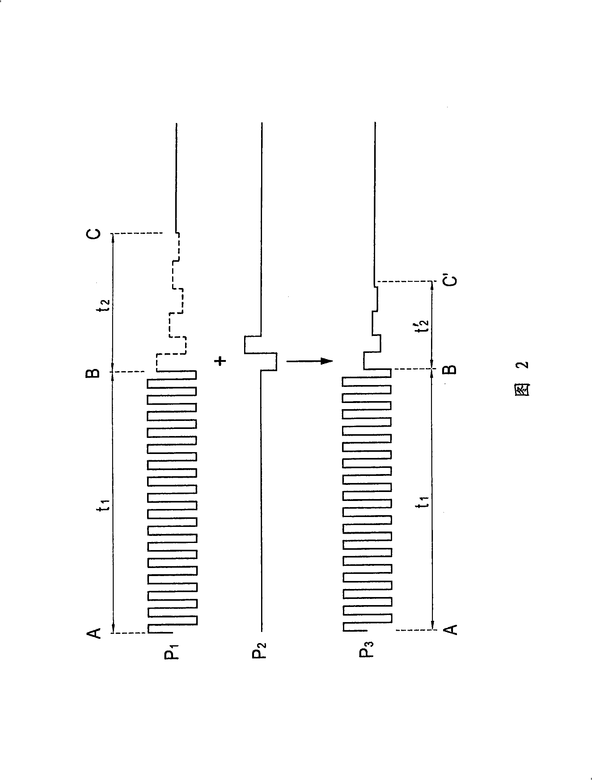
The invention provides a car reversing radar system with low aftershock and a method for emitting the signal of the car reversing radar with low aftershock, which comprises a receiving and emitting sensing unit, an ultrasonic emitting circuit, an ultrasonic receiving circuit, a processing unit, an alarming unit and a storage unit, wherein, the receiving and emitting sensing unit comprises at least one piezoelectric ceramic piece; the processing unit can emit a control signal and a pulsing signal, wherein, the control signal has continuous positive and negative amplitude phases, and the initial amplitude of the pulsing signal has the same phase as the end amplitude of the control signal, which causes the receiving and emitting sensing unit to output an ultrasonic signal with low aftershock.

Description

technical field [0001] The invention relates to a reversing radar system, in particular to a reversing radar system with low aftershock. Background technique [0002] As shown in Figures 4 and 5, the existing reversing radar usually applies a voltage of an alternating frequency (usually a frequency of an ultrasonic frequency band, such as 40kHz) to both ends of a piezoelectric ceramic sheet, so that the piezoelectric ceramic sheet It changes the oscillation frequency and oscillation direction, and sends out an output ultrasonic signal. After the output ultrasonic signal leaves the piezoelectric ceramic sheet, it propagates in the air along a certain direction. If an obstacle is encountered during the propagation process, part of the ultrasonic signal will be reflected back to the piezoelectric ceramic sheet to form a reflected ultrasonic signal ( RS). The reflected ultrasonic signal (RS) will push the piezoelectric ceramic piece and make it vibrate, and then make the two e...

Claims


Application Information

Patent Timeline
IPC IPC(8): G01S15/93
Inventor 李世雄
Owner 李世雄
Learn More