Lens unit and lens module using the same as well as flat panel display

A technology of lens unit and lens module, applied in the direction of lenses, instruments, optical components, etc.

Inactive Publication Date: 2008-11-12
INNOLUX CORP
View PDF0 Cites 8 Cited by
  • Summary
  • Abstract
  • Description
  • Claims
  • Application Information

AI Technical Summary

Problems solved by technology

However, since half of the display area is covered during the entire period of 16.7 milliseconds between the first period and the second period, the brightness of the stereoscopic image displayed by the stereoscopic image display 100 is only half of that of a general two-dimensional image.
It can be seen that the known stereoscopic image display 100 still has many shortcomings to be improved.

Method used


Image

  • Lens unit and lens module using the same as well as flat panel display
  • Lens unit and lens module using the same as well as flat panel display
  • Lens unit and lens module using the same as well as flat panel display

Examples


Embodiment Construction

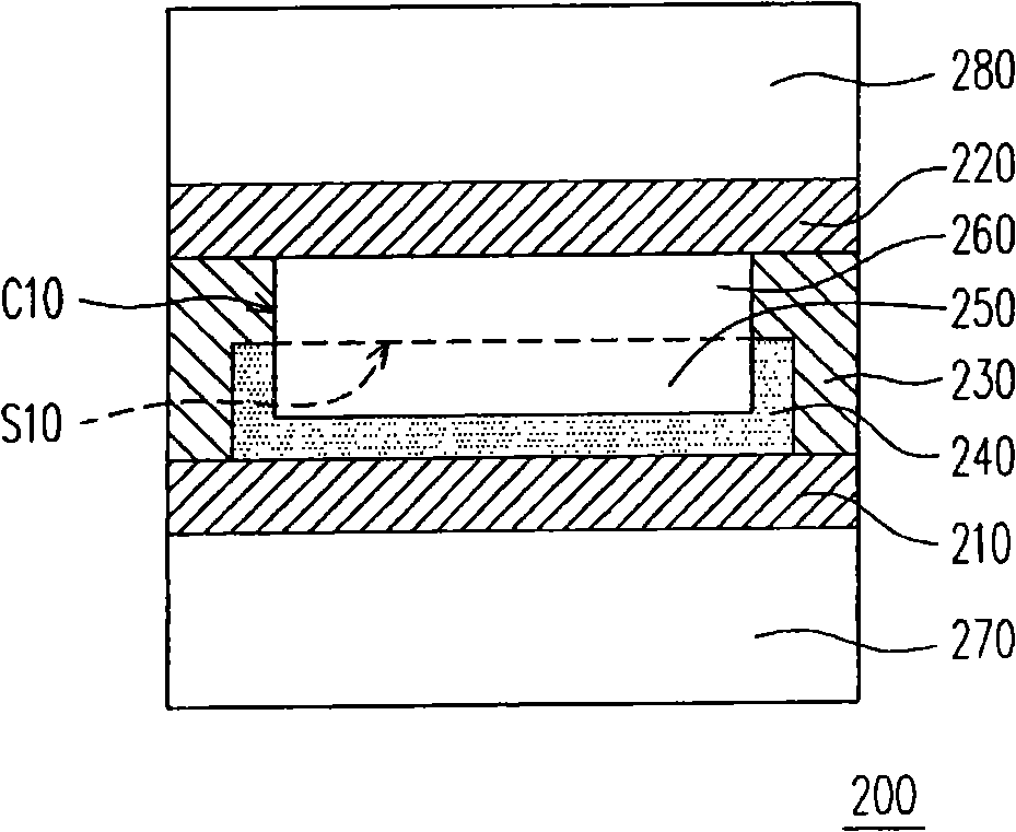
[0038] Figure 2A and Figure 2B is a schematic cross-sectional view of a lens unit according to an embodiment of the present invention before and after a voltage is applied. Please refer to Figure 2A , the lens unit 200 of this embodiment includes a first electrode 210 , a second electrode 220 , a cavity wall 230 , a non-polar liquid 250 and a conductive liquid 260 . Wherein, the cavity wall 230 is located between the first electrode and the second electrodes 210 and 220 , and forms a cavity C10 together with the first and second electrodes 210 and 220 . The non-polar liquid 250 is filled in the chamber C10 near the first electrode 210 , and the conductive liquid 260 is filled in the chamber C10 near the second electrode 220 . In addition, the conductive liquid 260 and the non-polar liquid 250 are immiscible, so there is an interface S10 between the conductive liquid 260 and the non-polar liquid 250 .

[0039]In addition, the lens unit 200 of this embodiment may further ...


PUM


Abstract

The invention relates to a lens unit which comprises a first electrode, a second electrode, a cavity wall, non-polar liquid and conducting liquid. The cavity wall is positioned between the first electrode and the second electrode and forms a chamber with the first electrode and the second electrode. A first material is arranged on the surface of the first electrode and the surface of the first electrode adjacent to the cavity wall in the chamber. The non-polar liquid is filled at one side of the chamber close to the first electrode. The conducting liquid is filled at one side of the chamber close to the second electrode, and the conducting liquid and the non-polar liquid are immiscible. The lens unit can be applied to a lens module and a flat plate display.

Description

field of invention [0001] The present invention relates to a lens unit, a lens module using the lens unit, and a flat panel display, and in particular to an active lens unit, a lens module using the lens unit, and a flat panel display. Background technique [0002] In terms of the development of display technology, in addition to pursuing lightness, thinness and compactness, it is also hoped to achieve the goal of displaying stereoscopic images. At present, the stereoscopic display technology can be roughly divided into two ways that users need to wear specially designed glasses or watch directly with naked eyes. Now, glasses-wearing stereoscopic display technology has matured and is widely used in some special purposes such as military simulation or large-scale entertainment, but the inconvenience and discomfort of wearing glasses makes this type of technology difficult to popularize. Therefore, the naked-eye stereoscopic display technology has gradually developed and beco...

Claims


Application Information

Patent Timeline
Patent Type & Authority Applications(China)
IPC IPC(8): G02B3/14G02B27/22G02F1/1335G09F9/00
Inventor 吴善德
Owner INNOLUX CORP
Why Eureka
Try Eureka