Autostereoscopic 3D image display apparatus using micro lens array

Inactive Publication Date: 2015-04-02
ELECTRONICS & TELECOMM RES INST
View PDF2 Cites 7 Cited by
  • Summary
  • Abstract
  • Description
  • Claims
  • Application Information

AI Technical Summary

Benefits of technology

[0020]The upper electrode coated partially on the upper portion of the lens can cause th

Problems solved by technology

The methods requiring the glasses (i.e., stereoscopic) are single-view methods and thus cannot realize motion parallax.
Accordingly, same images are projected regardless of the positions of the viewers' eyes, and thus the same image is shown to a viewer even if the viewer changes the position, failing to provide

Method used


Image

  • Autostereoscopic 3D image display apparatus using micro lens array
  • Autostereoscopic 3D image display apparatus using micro lens array
  • Autostereoscopic 3D image display apparatus using micro lens array

Examples


Embodiment Construction

[0025]Hereinafter, certain embodiments of the present invention will be described in detail with reference to the accompanying drawings. Any substantially identical elements in the description below and accompanying drawings will be assigned with same reference numerals and will not be redundantly described. Moreover, whenever it is deemed that providing detailed description of any relevant known function or element will inadvertently evade the gist of the present invention, such description will be omitted.

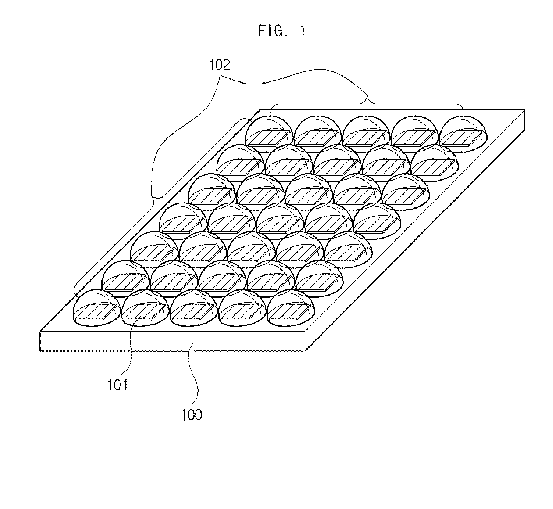
[0026]FIG. 1 shows a 3D image display apparatus in accordance with an embodiment of the present invention. As illustrated in FIG. 1, the 3D image display apparatus in accordance with the present embodiment includes an image display apparatus 100, a micro lens array 102, which is arranged above the image display unit 100 and configured to change a focus of an image displayed by the image display unit 100, and, although now shown, an electrode coated on the micro lens array 102. Th...


PUM


Abstract

An autostereoscopic 3D image display apparatus is disclosed. The autostereoscopic 3D image display apparatus in accordance with an embodiment of the present invention can include: an image display unit configured to display an image; a micro lens array arranged above the image display unit and configured to vary a focus of an image from the image display unit; and an electrode coated on the micro lens array and configured to have an electric signal supplied thereto to cause transformation of the micro lens array.

Description

CROSS-REFERENCE TO RELATED APPLICATIONS[0001]This application claims the benefit of Korean Patent Application No. 10-2013-0116156, filed with the Korean Intellectual Property Office on Sep. 30, 2013, the disclosure of which is incorporated herein by reference in its entirety.BACKGROUND[0002]1. Technical Field[0003]The present invention relates to a 3D image display apparatus, mores specifically to an autostereoscopic 3D image display apparatus.[0004]2. Background Art[0005]While there are many ways to realize a 3D image, they are mainly divided into two groups, depending on whether glasses are worn or not. The methods requiring the glasses (i.e., stereoscopic) are single-view methods and thus cannot realize motion parallax. Accordingly, same images are projected regardless of the positions of the viewers' eyes, and thus the same image is shown to a viewer even if the viewer changes the position, failing to provide the realistic and animated senses. Moreover, the requirement of having...

Claims


Application Information

Patent Timeline
IPC IPC(8): G02B27/22H04N13/307
CPCG02B27/2214G02B3/14G02B26/0875H04N13/356H04N13/307G02B30/28G02B26/004G02B30/27
Inventor PARK, BONG-JEKYUNG, KI-UKYUN, SUNG-RYULPARK, SUN-TAK
Owner ELECTRONICS & TELECOMM RES INST
Why Eureka
Try Eureka