Focusing structure for LED lamp

a technology of led lamps and focusing structures, which is applied in the direction of semiconductor devices for light sources, planar light sources, lighting and heating apparatus, etc., can solve the problems of inconvenient replacement of lenses when in use, inability of led lamps to adjust focus, and inability to influence the illumination effect of light loss

Inactive Publication Date: 2014-11-13
MAINHOUSE (XIAMEN) ELECTRONICS CO LTD
View PDF3 Cites 8 Cited by
  • Summary
  • Abstract
  • Description
  • Claims
  • Application Information

AI Technical Summary

Benefits of technology

[0014]The lens assembly of the present invention comprises a plurality of sets of lenses with different angles. When in use, the lens assembly is rotated for the lenses to align with the LED chips to achieve focus adjustment function. This structure changes the distance between the chips and the lenses for adjusting focus so there is no light loss to ensure illumination effect and to achieve various is focus adjustment functions.

Problems solved by technology

This kind of LED lamp is unable to adjust focus.
However, it is very inconvenient to replace the lenses when in use.
This way causes light loss to influence the illumination effect.

Method used


Image

  • Focusing structure for LED lamp
  • Focusing structure for LED lamp
  • Focusing structure for LED lamp

Examples


first embodiment

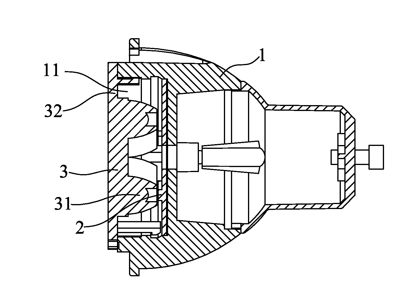
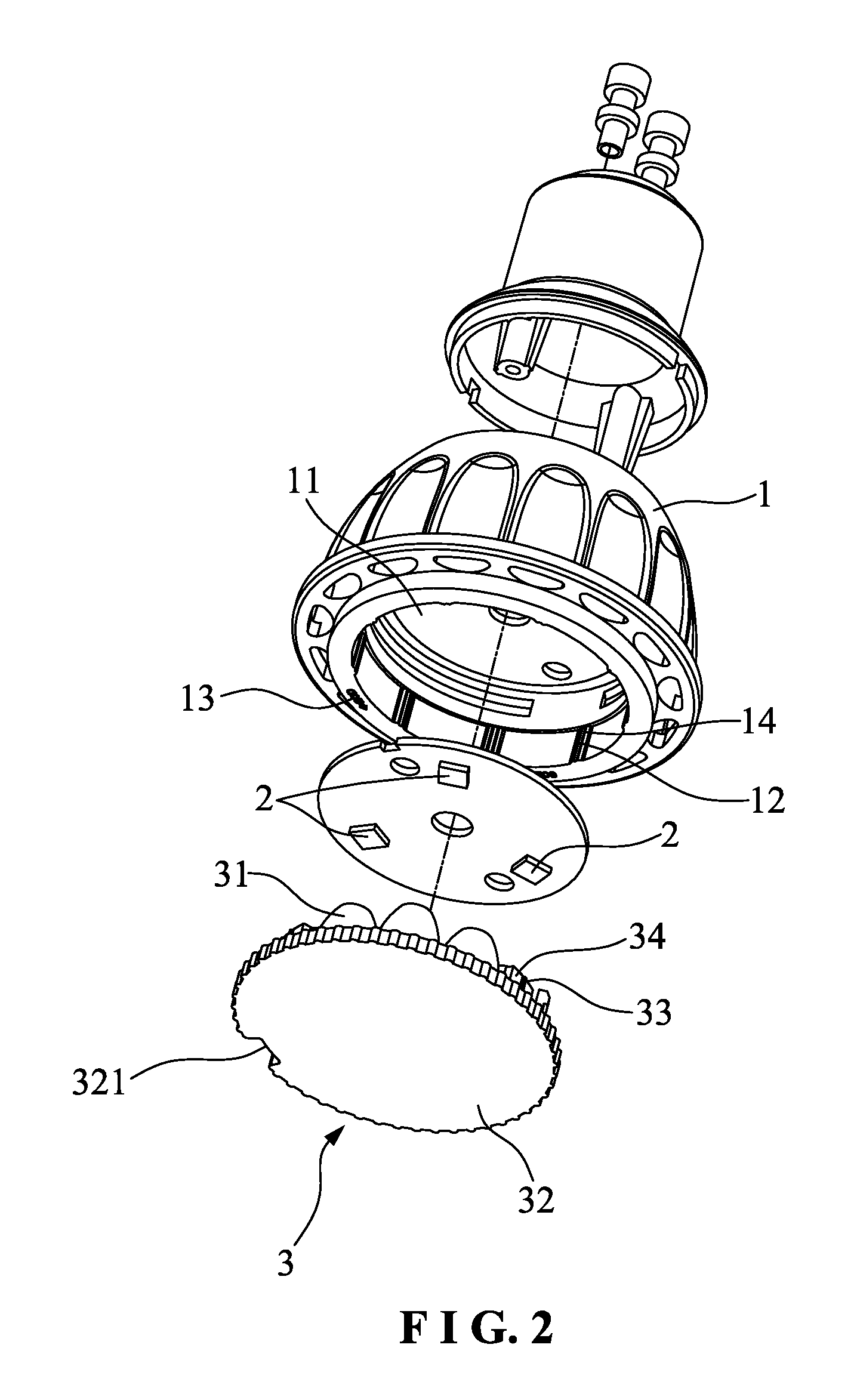
[0038]The present invention discloses a focusing structure for an LED lamp. As shown in FIG. 2 to FIG. 6, the present invention comprises a main body 1, an LED chip 2 mounted in the main body 1, and a lens assembly 3 mounted at the front end of the main body 1. The LED chip 2 may be one, two or more according to the demand. This embodiment has three LED chips 2. The three LED chips 2 are located at the same circumference.

[0039]The lens assembly 3 comprises at least two sets of lenses 31 with different degrees. Each set of lenses 31 corresponds in position to the LED chips 2 at the same circumference. This embodiment has two sets of lenses 31. One set of lenses 311 is 20 degrees, and the other set of lenses 312 is 40 degrees. In this embodiment, the three LED chips 2 are evenly arranged at the same circumference. Each set of lenses 31 has three lenses, namely, the two sets of lenses have six lenses 31. The six lenses 31 are evenly arranged at the same circumference corresponding to t...

third embodiment

[0050]In the third embodiment, the LED lamp also comprises the LED chips 2 mounted in the main body 1. The lens assembly 3 is mounted at the front end of the main body 1. This embodiment has three LED chips 2. The difference of this embodiment is that the LED chips 2 are semi-spherical chips. Similarly, the lens assembly 3 has at least two sets of lenses 31 with different degrees. The bottom of each lens 31 of this embodiment has a recess 35. Each set of lenses 31 corresponds in position to the LED chips 2. This embodiment has three sets of lenses 31, namely, three 20 degree lenses 311, three 40 degree lenses 312 and three 60 degree lenses 313. The lens assembly 3 and the main body 1 are rotatably engaged with each other.

[0051]Furthermore, the connection of the lens assembly 3 and the main body 1 is described hereinafter. The main body 1 has at least one positioning post 15 thereon. The lens assembly 3 further comprises a fixing disc 32 for mounting the lenses 31. The fixing disc 32...

fourth embodiment

[0057]As shown in FIG. 21 and FIG. 22, the present invention is substantially similar to the aforesaid embodiments with the exceptions described hereinafter. This embodiment has ten LED chips 2. One is disposed on the axis of the lamp, and the others are divided into two sets evenly disposed at two concentric circumferences. Three LED chips are disposed around the small circumference, and six LED chips are disposed around the big circumference. Except the lens corresponding to the central chip 2, this embodiment has three sets (two sets or more) of lenses 31 with different degrees, namely, three 20 degree lenses 311, three 40 degree lenses 312 and three 60 degree lenses 313. The three lenses 311, 312, 313 of each set correspond in position to the corresponding LED chips 2 at the same circumference. In this embodiment, the lens assembly 3 is rotated for the lenses 31 of each set to be aligned with the corresponding LED chips 2 to adjust focus. The lens assembly 3 and the main body 1 ...


PUM


Abstract

A focusing structure for an LED lamp is provided. LED chips are provided in a main body of the LED lamp, a front end of the main body 1 is provided with a lens assembly. At least one of the LED chips 2 is not located on the axis of the LED lamp, and at least two groups of lenses with different degrees are provided on the lens assembly, the location of each group of lenses corresponding to a corresponding LED chip on the same circumference, and the lens assembly is connected to the main body with structures capable of relatively rotating and snap-fitting. The LED lamp can achieve the focusing function by rotating the lenses assembly to make the lenses with different degrees correspond to the LED chips. This structure has no light loss and can achieve the focusing function of various focal distances.

Description

BACKGROUND OF THE INVENTION[0001]1. Field of the Invention[0002]The present invention relates to an LED lamp, and more particularly to a focusing structure for an LED lamp.[0003]2. Description of the Prior Art[0004]An LED lamp comprises LED chips and lenses in front of the LED chips so as to focus the light. FIG. 1 is an exploded view of a conventional LED lamp. The LED lamp comprises a main body 1′, LED chips 2′ mounted in the main body 1′, and a lens assembly 3′ mounted at the front end of the main body 1′. This kind of LED lamp is unable to adjust focus. If the user wants to change the angle of illumination, it is necessary to replace with lenses with different angles. However, it is very inconvenient to replace the lenses when in use.[0005]An improved LED lamp on the market can adjust its brightness and illuminating range. Chinese Utility Model Publication No. CN202065923U published on Dec. 7, 2011 discloses a light adjustment structure of an LED lamp. This LED lamp is like the ...

Claims


Application Information

Patent Timeline
Patent Type & Authority Applications(United States)
IPC IPC(8): F21K99/00
CPCF21K9/50F21V5/007F21V14/06F21Y2105/10F21K9/233F21Y2115/10F21V17/02
Inventor ZHOU, NANQING
Owner MAINHOUSE (XIAMEN) ELECTRONICS CO LTD
Why Eureka
Try Eureka