DC/DC circuit

A circuit and inductance technology, applied in the field of DC/DC circuit structure, can solve the problems of limited driving capacity, large switch tube area, and inability to use power supply equipment, etc., to achieve low cost, simple and feasible improvement of circuit structure, and flexible input and output voltage range. changeable effect

Active Publication Date: 2011-03-02
BYD SEMICON CO LTD
View PDF0 Cites 0 Cited by
  • Summary
  • Abstract
  • Description
  • Claims
  • Application Information

AI Technical Summary

Problems solved by technology

[0004] In order to realize the special application where the output voltage varies linearly with the input voltage, the following two schemes can be adopted considering the existing products in the market: 1. Use a charge pump to directly realize a certain step-up or step-down proportional relationship between the output voltage and the input voltage , but there are two defects in this scheme. One is that as mentioned above, it cannot provide a large current output (for example, more than 0.5A), and the other is that it is inconvenient to realize the output voltage V OUT with input voltage V IN Any proportional relationship, because the more special the ratio value, the more switch tubes are required inside the IC, especially in high current applications, which will result in a large switch tube area, and the charge pump is generally used as 1.5 times, 2 times or 3 times
2. Use a simple operational amplifier to realize V OUT with V IN A certain proportional relationship, but the driving capacity is limited, it cannot be used as a power supply device, and it can only realize step-down, and it is impossible to realize the step-up of the power supply
[0005] The DC / DC converter itself has the characteristics of high efficiency and high current, but the existing technology cannot make its output voltage and input voltage follow any linear relationship

Method used


Image

  • DC/DC circuit
  • DC/DC circuit
  • DC/DC circuit

Examples


Embodiment 1

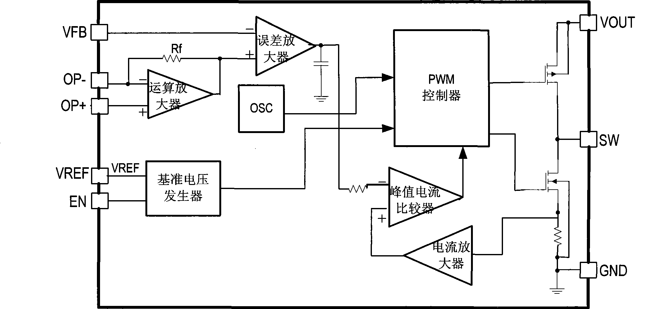
[0032] The DC / DC circuit in this example is applied as a DC / DC converter, and its basic working principle is PWM type working in fixed frequency and current control mode. This example is a step-up DC / DC converter, and its block diagram is as follows: figure 1 As shown, including PWM controller, current amplifier, peak current comparator, error amplifier, reference voltage generator, main switch and synchronous switch, etc.; the output of the error amplifier is connected to the inverting input of the current comparator, and the peak current comparator The non-inverting input terminal of the error amplifier is connected to the output terminal of the current amplifier, and the output terminal of the peak current comparator is connected to the control terminal of the PWM controller; the inverting input terminal of the error amplifier is set as the output voltage feedback terminal VFB for coupling with the output voltage; the main switch , The control end of the synchronous switch ...

Embodiment 2

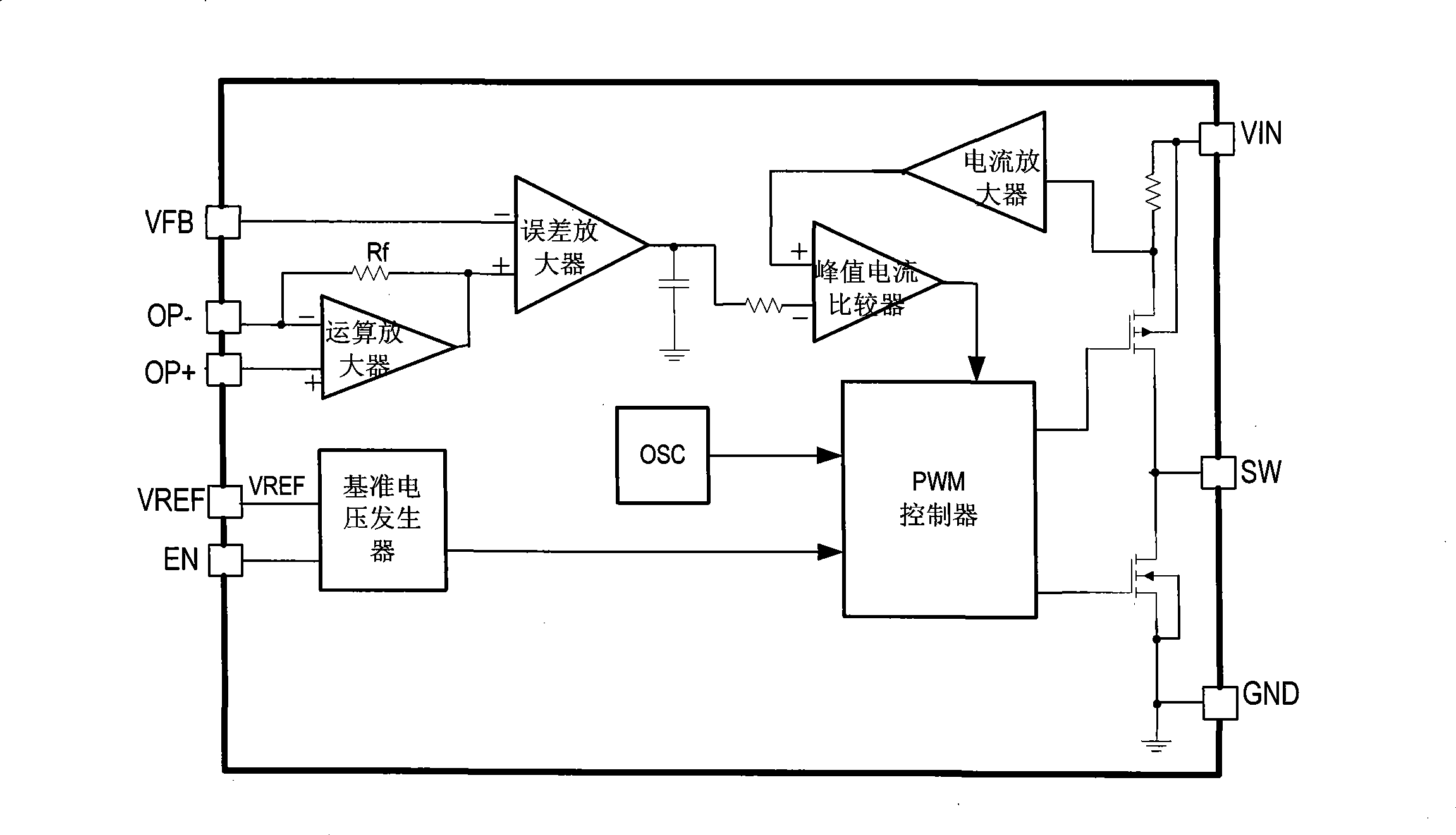
[0063]The DC / DC circuit in this example is applied as a DC / DC converter, such as figure 2 Shown is the block diagram of the step-down DC / DC converter in this example. The main switch uses a PMOS switch tube, and the synchronous switch uses an NMOS switch tube. The basic principle is the same as that of the step-up DC / DC converter, and will not be repeated here. . Similarly, the error amplifier non-inverting input voltage V EA+ Set to a variable voltage value, and through the operational amplifier can make the error amplifier non-inverting input voltage V EA+ with input voltage V IN In this way, the output voltage also forms a linear follow-up relationship with the input voltage while boosting, that is,

[0064] V OUT =A·V IN +B type 2

[0065] Figure 4 This is a typical application circuit for the step-down DC / DC converter in this example to realize the linear follow-up relationship of the input and output voltages in Equation 2. In order to realize the linear follow-...

Embodiment 3

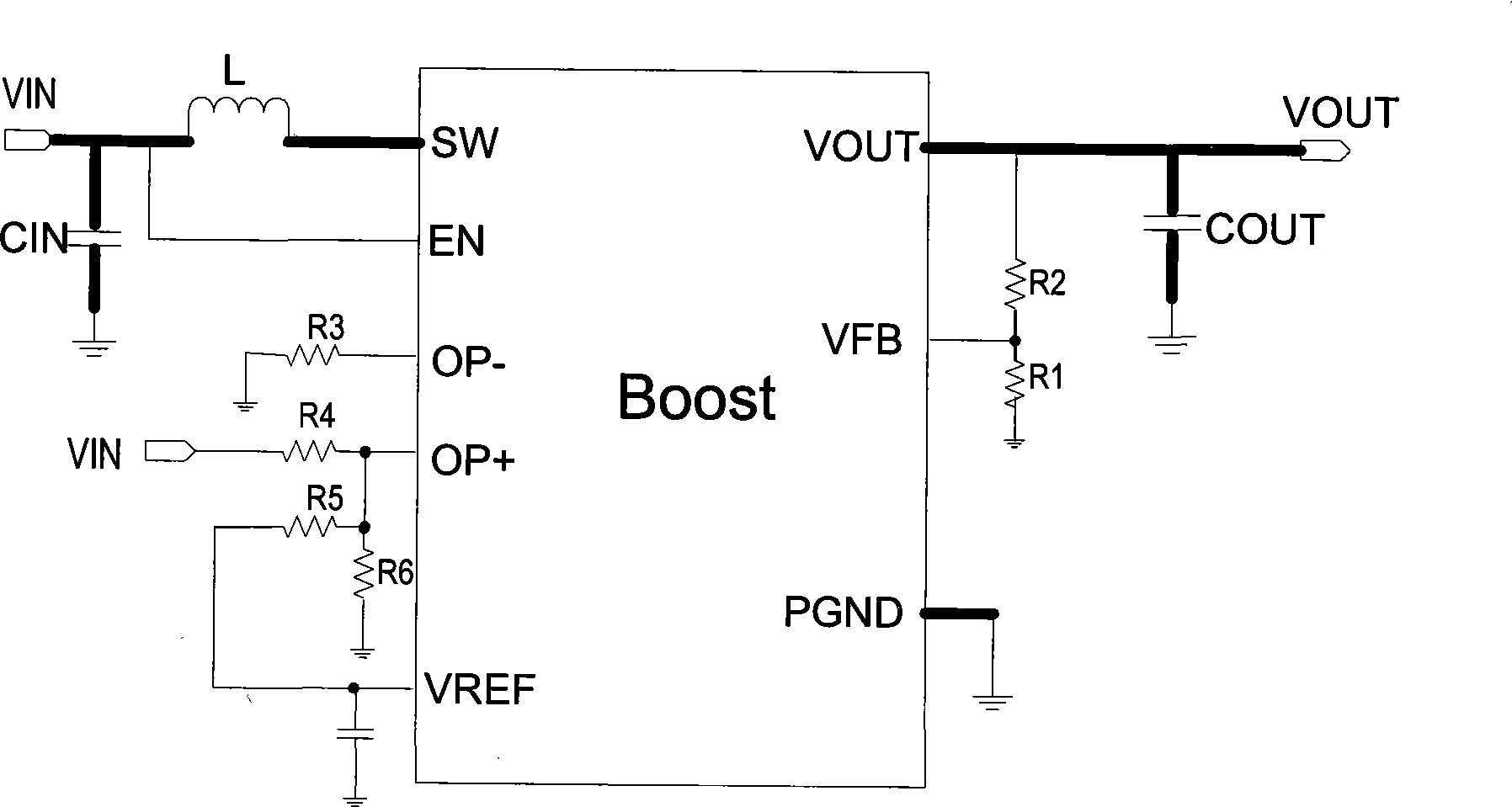
[0068] The DC / DC circuit in this example is applied as a DC / DC converter, such as Figure 5 As shown, this example is another typical application circuit of a step-up DC / DC converter, in which the basic principle of a step-up DC / DC is as follows figure 1 shown. The subtractor structure is implemented by the operational amplifier, and the output voltage of the subtractor is sent to the non-inverting input terminal of the error amplifier. The error amplifier non-inverting input voltage V EA+ Set to a variable voltage value, and through the operational amplifier can make the error amplifier non-inverting input voltage V EA+ with input voltage V IN In this way, the output voltage also forms a linear follow-up relationship with the input voltage while boosting, that is,

[0069] V OUT =A·V IN -B Formula 9

[0070] Such as Figure 5 As shown, in the step-up DC / DC converter, in order to realize the linear following relationship described in Equation 9, an inductor L can be co...


PUM


Abstract

The invention discloses a DC / DC circuit, comprising a PWM controller, a current amplifier, a peak current comparator, an error amplifier, a main switch, a synchronous switch and also an operational amplifier. The non inverting input end of the operational amplifier is used for coupling with input voltage or voltage reference, or used for coupling with the input voltage and the voltage reference; the inverting input end of the operational amplifier is used for coupling with the voltage reference or ground, and the output end thereof is connected with the non inverting input end of the error amplifier. As a DC / DC basic structure is adopted, the operational amplifier leads the non inverting input end voltage of the error amplifier to follow the input voltage linearly, thus realizing the linear following relation between the output voltage and the input voltage. As the DC / DC basic structure is adopted, the circuit provided by the invention has the advantages of DC / DC to guarantee the highefficiency of the output of the voltage and great driving capacity.

Description

【Technical field】 [0001] The invention relates to a DC / DC circuit structure. 【Background technique】 [0002] There are mainly three types of voltage regulators in current portable power management IC products, namely: low-dropout linear regulators, non-isolated DC / DC converters and charge pumps. Among them, the low-dropout linear regulator can only be used for step-down. The advantages are small ripple, few peripheral components, and low cost, but it generates a lot of heat and low efficiency, especially in the case of large voltage drop and high current. Therefore, it is generally Applied to output current within 300mA, up to about 500mA. The DC / DC converter can realize step-up, step-down and buck-boost, and requires external magnetic components such as inductors. The application circuit is relatively complicated. Because it is a switch control mode, the ripple is large. The biggest advantage is high efficiency and can be adapted to Applications with high current requirem...

Claims


Application Information

Patent Timeline
Patent Type & Authority Patents(China)
IPC IPC(8): H02M3/28
Inventor 屈擘赵一飞尹友云
Owner BYD SEMICON CO LTD
Why Eureka
Try Eureka