DC/DC circuit
A circuit and resistor technology, applied in the field of DC/DC circuit structure, can solve the problems of limited drive capacity, large switch tube area, unusable power supply equipment, etc., achieve low cost, simple and feasible improvement of circuit structure, and flexible input and output voltage range changeable effect
- Summary
- Abstract
- Description
- Claims
- Application Information
AI Technical Summary
Problems solved by technology
Method used
Image
Examples
Embodiment 1
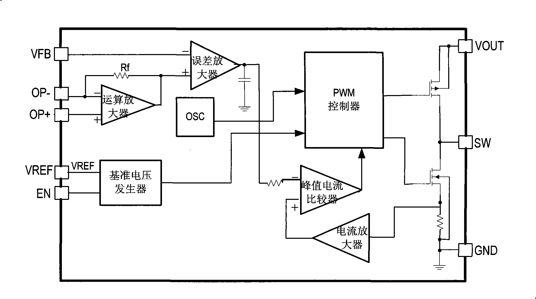
[0032] The DC / DC circuit in this example is applied as a DC / DC converter, and its basic working principle is PWM type working in fixed frequency and current control mode. This example is a step-up DC / DC converter, and its block diagram is as follows: figure 1 As shown, including PWM controller, current amplifier, peak current comparator, error amplifier, reference voltage generator, main switch and synchronous switch, etc.; the output of the error amplifier is connected to the inverting input of the current comparator, and the peak current comparator The non-inverting input terminal of the error amplifier is connected to the output terminal of the current amplifier, and the output terminal of the peak current comparator is connected to the control terminal of the PWM controller; the inverting input terminal of the error amplifier is set as the output voltage feedback terminal VFB for coupling with the output voltage; the main switch , The control end of the synchronous switch ...
Embodiment 2
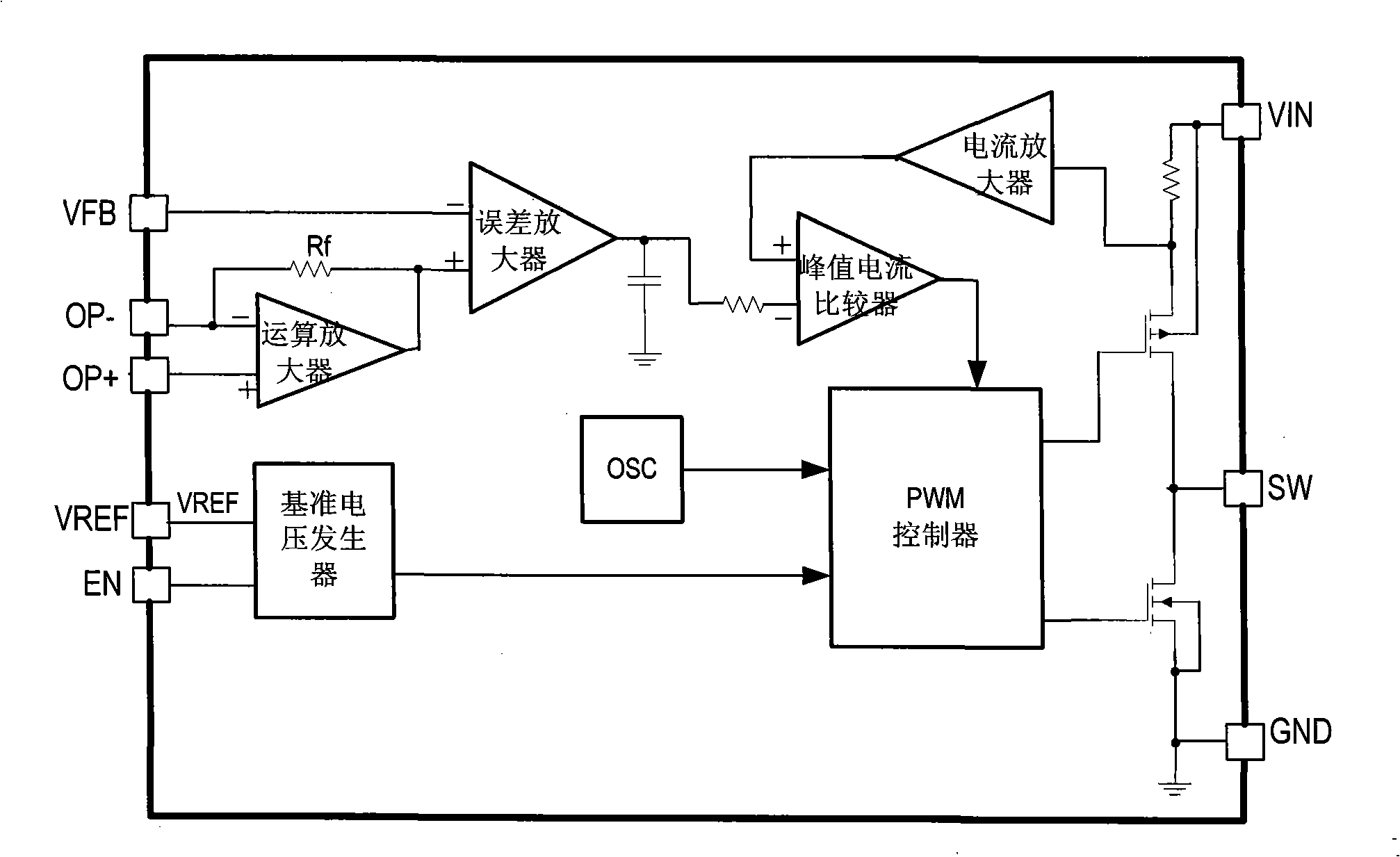
[0063] The DC / DC circuit in this example is applied as a DC / DC converter, such as figure 2 Shown is the block diagram of the step-down DC / DC converter in this example. The main switch uses a PMOS switch tube, and the synchronous switch uses an NMOS switch tube. The basic principle is the same as that of the step-up DC / DC converter, and will not be repeated here. . Similarly, the error amplifier non-inverting input voltage Y EA+ Set to a variable voltage value, and through the operational amplifier can make the error amplifier non-inverting input voltage V EA+ with input voltage VIN In this way, the output voltage also forms a linear follow-up relationship with the input voltage while boosting, that is,
[0064] V OUT =A·V IN +B Formula 2
[0065] Figure 4 This is a typical application circuit for the step-down DC / DC converter in this example to realize the linear follow-up relationship of the input and output voltages in Equation 2. In order to realize the linear follo...
Embodiment 3
[0068] The DC / DC circuit in this example is applied as a DC / DC converter, such as Figure 5 As shown, this example is another typical application circuit of a step-up DC / DC converter, in which the basic principle of a step-up DC / DC is as follows figure 1 shown. The subtractor structure is implemented by the operational amplifier, and the output voltage of the subtractor is sent to the non-inverting input terminal of the error amplifier. The error amplifier non-inverting input voltage V EA+ Set to a variable voltage value, and through the operational amplifier can make the error amplifier non-inverting input voltage V EA+ with input voltage V IN In this way, the output voltage also forms a linear follow-up relationship with the input voltage while boosting, that is,
[0069] V OUT =A·V IN -B Formula 9
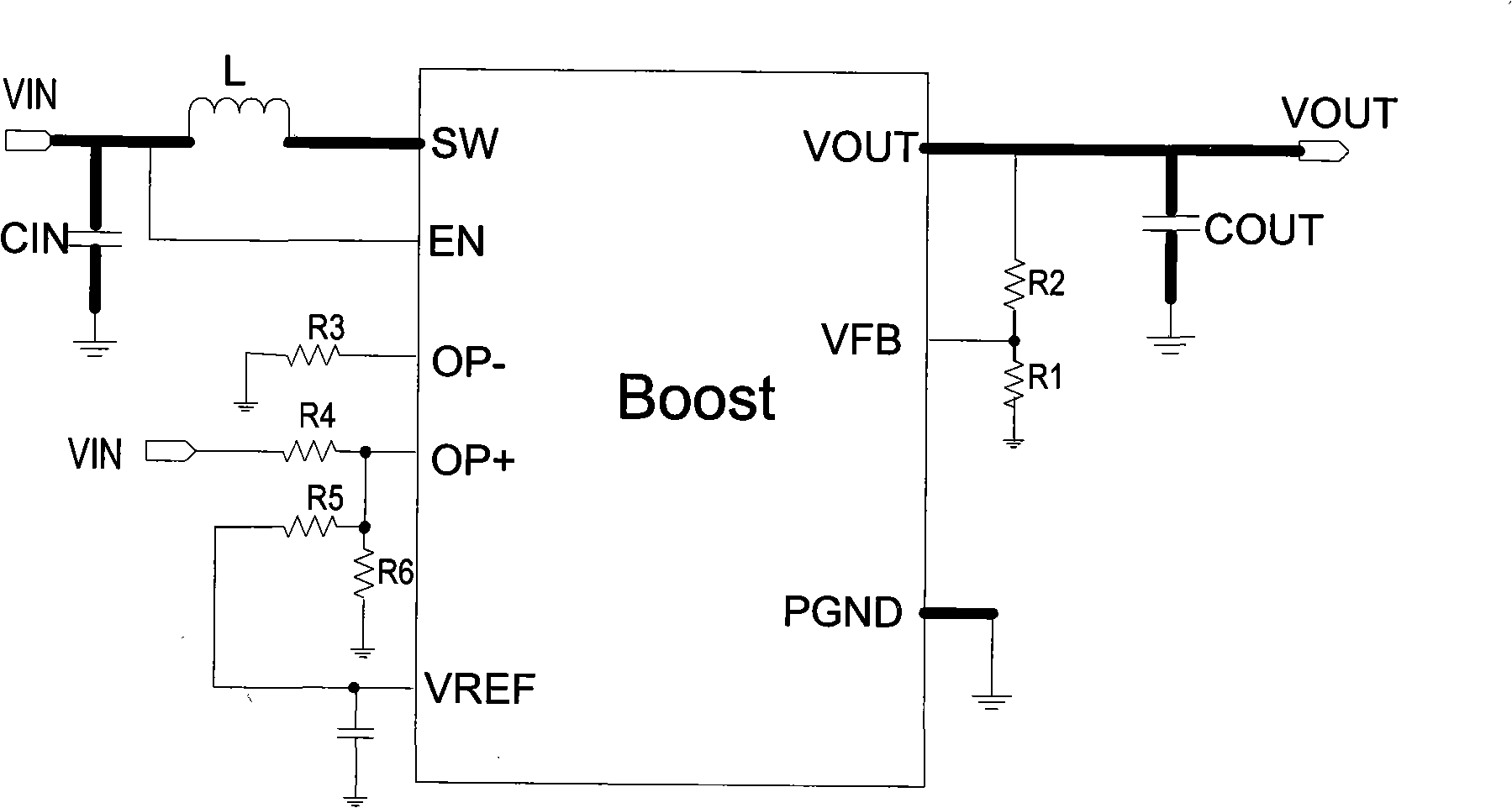
[0070] Such as Figure 5 As shown, in the step-up DC / DC converter, in order to realize the linear following relationship described in Equation 9, an inductor L can be co...
PUM
 Abstract
Description
Claims
Application Information
 - R&D
- Intellectual Property
- Life Sciences
- Materials
- Tech Scout
- Unparalleled Data Quality
- Higher Quality Content
- 60% Fewer Hallucinations
Browse by: Latest US Patents, China's latest patents, Technical Efficacy Thesaurus, Application Domain, Technology Topic, Popular Technical Reports.
© 2025 PatSnap. All rights reserved.Legal|Privacy policy|Modern Slavery Act Transparency Statement|Sitemap|About US| Contact US: help@patsnap.com


